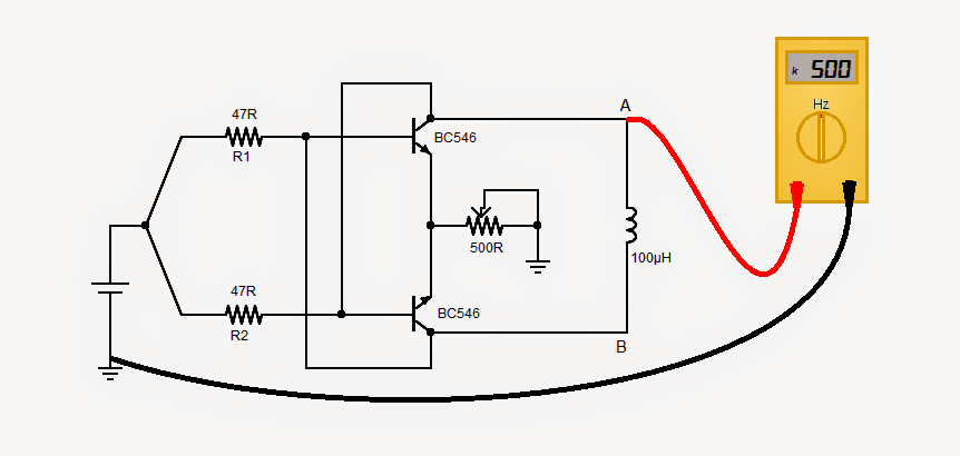
Right here a easiest yet quite precise inductance meter is introduced, which is often developed within couple of minutes. Moreover, the circuit may be powered-up with a single 1.5V cell. In spite of this, a frequency meter could well be needed to work-out the inductance.
The circuit is fairly self-explanatory in which, two NPN transistors are cross-coupled to form a flip-flop oscillator. The values of R1 and R2 could possibly be anything between 47 - 100R. The frequency of the oscillation is oppositely proportional to the inductance and it could be measured with the following formula:
Frequency (kHz) = 50,000 / Inductance (uH)
CALIBRATION:
In the beginning the circuit needs to be calibrated utilizing a known inductor, as identified below:
Think, we certainly have an inductor of 100uH. Putting the value of inductor (100uH) in the above formula, we get 500kHz.
Hook up the inductor cross point A & B and power on the circuit. It is going to begin oscillating.
Attach the frequency meter at point A or B and ground.
Regulate the POT until the meter reads 500kHz. Now the circuit is calibrated.
INDUCTANCE MEASUREMENT:
Hook up an unidentified inductor across A & B.
Power on the circuit and study the frequency at point A or B.
The above formula may also be published as:
Inductance (uH) = 50, 000 / Frequency (kHz)
Placing the value of frequency in this formula, the value of the inductor can be obtained.
Waveform Image:
