


You may have most likely discover these types of great high power, high effectiveness LED devices and asked yourself how can you create these kinds of? Right here we discover ways to build a 100 watt LED flashlight out of it?
The post revises the datasheet of this LED module and describes a basic driver circuit that are available for running it securely for the meant illumination purpose.
Until now we certainly have became well versed in LEDs with quite lesser known benefits and functions. In spite of this the existing write-up discovers just how a LED module according to 100 watts may be in fact useful for lighting a house at costs almost certainly 5 times less than the standard lighting devices.
Requirements and Benefits
We certainly have all analyzed a whole lot regarding LEDs and about their high-efficiency with power consumption. The LED technology has assisted us to design and include quite high strength lighting installations at minimal consumptions when compared with the other regular type of illuminating ideas.
Lower power consumption includes low heat emissions, which once again is an extra characteristic and helps to maintain the essential matter of global warming at bay when LEDs are used.
As days go by, technology maintains on enhancing and you can easily experience a lot of amazing and incredible outcomes using these unbelievable lighting devices.
The 100 watt LED module is certainly one this kind of marvel of latest science which includes produced a discovery in the vast field of LED lighting.
And in addition, the device has the capacity to produce a fabulous 6500 lumens of light power at a intake of mere 100 watts, but the fascinating part is the size, which can be hardly 40 square mm.
The preserving created by these products is anticipated to be five times a lot more than almost every other kind of light creating device and the if we compare the specific strength of 6500 lumens, that represents too much 500 watts light power that may be obtained from a halogen lamp.
Let’s talk about the crucial specs of this awesome LED briefly and in such a means that even a layman realizes:
100 Watt LED Datasheet and Requirements
Generally the desired color is white, as that generates the most affordable and suitable lighting for all functions.
The power used is 100 watts for maximum overall performance.
The emanated heat for the specific white color is up to 6000 Kelvin.
The power of light produced with the above specifications is an incredible 6500 lumens.
Standard working voltage of the device is about 35 volts.
The current needed for generating the above light strength is just about 3 Amps.
ESD level is safe and extremely high up to 4000 V.
The safe working temperature level is very wide, starting from minus 40 to 110 degrees Celsius.
The most effective position of watching can be broad, up to 120 degree.
Dimension of the unit is truely mini, the height being 4.3 mm, length 56 mm and width 40 mm only.
The requirement narrated are adequate for enlightening a 20 square meter space completely, just about at flood light levels ….. complex.
Benefits
The benefits incorporate the following:
High power light output without degradation even though lengthy uses.
Highly robust mechanical requirements, concerning much less deterioration and high opposition to altering atmospheric hostilities.
The efficiency is constantly best all through the functioning life.
Having mentioned the above features of the suggested 100 watt LED lamp, it might be attractive to additionally understand concerning a helpful suggested circuit which may be employed for driving or running the device at protected levels.
Application Circuit (Making a 100 watt LED flood Light Circuit)
A basic two transistor, strong current limiter, LED driver circuit, which you can use for transforming the above talked about device into a 100 watt LED flashlight or to become more precise, a floodlight is identified below:
The circuit of a 100 watt LED flood light demonstrated below continues to be mentioned in few of my other content as well, owing its adaptable and rather very simple design; the circuit turns into very appropriate in places where current limiting at low costs evolves into a problem. However the talked about designs mainly handled low current applications, the current circuit is in particular meant for managing high currents and up to 100 watts and more power.
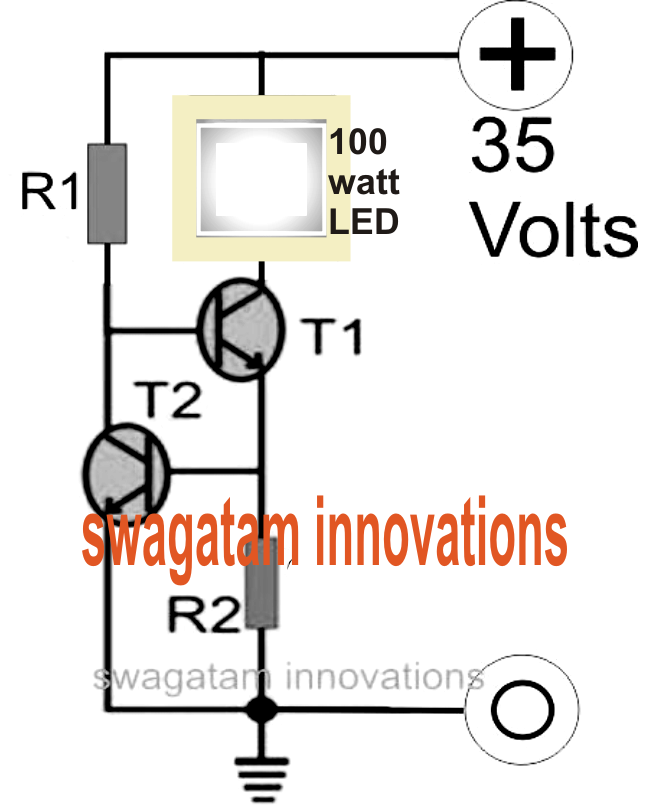

Investigating the figure we are able to observe a few transistors are combined with each other such that the base of the upper transistor T1 evolves into the collector load of the bottom transistor T2.
The upper transistor T1 which in fact possess the LED current is pretty susceptible on its own, as well as being not equipped to manage the quantity of current by means of itself and the LED.
On the other hand because the base current of this transistor chooses the quantity of collector current which could cross, it basically signifies that by limiting its base current to some safe stipulated levels, it may be easy to continue the all round usage within bearable limitations.
A current sensing resistor attached at the emitter of T1 is employed to convert the current consumed, into a potential improvement, across it. This potential difference turns into the base activate for R2. In spite of this provided that this voltage is below 0.6 volts or simply below the minimum forward voltage drop of T2, T2 continues to be unresponsive, but as soon as it begins going above this value, causes T2 which often clamps the base voltage of T1, turning it into inactive. This immediate cut off of the base drive to T1 shuts the LED for some portion of a second, delivering the current and the potential decrease across the current decreasing resistor to zero. This motion reverts the circuit to its original posture and the LED is once again turned on. The method repeats several occasions per second to keep the LED and the current to safe and exactly reasonable limitations.
The value of R2 is computed in such a means that it maintains the potential improvement across on its own below 0.6 volts until the LED current gets to 100 watts, after which the minimizing method starts.
Caution: The LED ought to be installed on a properly fully optimized heatsink as per the specs offered in its datasheet..
For measuring R1 you can use the following formula:
R1 = (Us - 0.7)Hfe/Load Current,
where Us = supply voltage, Hfe = T1 forward current gain, Load current = LED current = 100/35 = 2.5 amps
R1 = (35 - 0.7)30/2.5
= 410 Ohms,
wattage for the above resistor could well be = 35 x (35/410) = 2.98 or 3 watts
Formula for calculating R2 is:
R2 = 0.7/LED current
R2 = 0.7/2.5 = 0.3 ohms,
wattage might be determined as = 0.7 x 2.5 = 2 watts