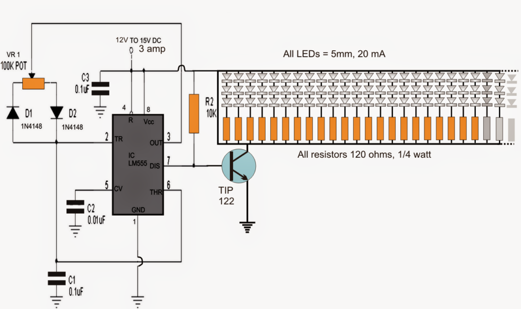
The submit talks about a 555 based PWM circuit which is often executed as a 150 nos or more LED light intensity controller circuit.
The figure demonstrates a PWM based LED intensity controller circuit implementing the IC 555.
IC 555 are widely employed in nearly all PWM based circuit applications as a result of their simple design and accurate PWM generation ability which can be adjustable starting from minimum to the maximum.
In the presented design the 555 IC is set up in its normal PWM mode with a slight variation in which it's discharge pin7 is utilized as the output rather than its normal pin3 which happens to be quite raised for the discharge function here.
The above configuration tends to make the performing a little more economical and permits the spaces of the duty cycles to be sharp even more precise.
Pin7 turns into to blame for producing negative pulses only for the connected transistor, although the positive pulses result from the 10 k resistor across the base and positive of the transistor.
VR1 is employed as the PWM control pot which almost offers a selection from zero to the highest supply voltage for the LEDs by way of changing ON/OFF duty cycles as based on the setting of the 100k pot
TIP122 is rated to hold upto 5 amp with sufficient heatsinking which means greater than 150 LEDs rated at 20 mA each may be offered with the device as demonstrated in the circuit diagram.
