


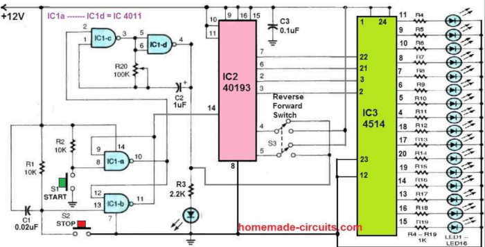
In this really cool reverse forward LED chaser circuit concept we are essentially turning on and off a sequence of 16 LEDs one after another using a 24-pin decoder IC.
We are talking about the CMOS 4514 binary-to-decimal decoder here which is labeled as IC3. This IC uses a four-bit binary input to activate each of its 16 outputs in sequence.
How it Works
Now this binary input is provided by another IC, specifically the IC2 40193. This chip functions as a binary up/down counter capable of counting either forward or backward depending on how we set it up.

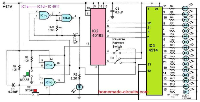
We have also got an astable oscillator in the mix, formed by two gates (IC1c and IC1d) from our trusty quad NAND gate IC4011. The frequency of this oscillator is controlled by components C2 and R20—so we can tweak it to our liking.
Additionally two other gates (IC1-a and IC1-b) are configured as a set-reset flip-flop latching circuit. We use switches S1 and S2 to manage the start and stop functions respectively—it is pretty straightforward! Meanwhile, switch S3 controls whether our sequencing goes forward or backward.
So here is how it all works: when switch S1 is pressed then it starts the oscillator by setting pin 2 of IC1c high. This causes pin 10 of IC1a to latch high at the same time.
Simultaneously if switch S3 determines whether to count up or down then pin 14 of IC2's reset input goes low—it depends on how we position those switches!
As our clock runs smoothly along its merry way then LEDs from LED1 all the way through LED16 turn on one at a time in sequence—looking super slick if I do say so myself!
If they have been activated once (or deactivated if counting down) then once all these LEDs have been activated once (or deactivated), our LED chasing sequence simply restarts until stopped with switch S2!
Parts List
| Component | Value / Part Number | Specifications | Description |
|---|---|---|---|
| Resistors | |||
| R1 | 10K | 1/4W, 5% tolerance | Pull-down resistor |
| R2 | 10K | 1/4W, 5% tolerance | Pull-up resistor |
| R3 | 2.2K | 1/4W, 5% tolerance | LED current limiter |
| R4 - R19 | 1K | 1/4W, 5% tolerance | LED current limiters |
| R20 | 100K | 1/4W, 5% tolerance | Timing resistor |
| Capacitors | |||
| C1 | 0.02µF | 50V, Ceramic | Debouncing capacitor |
| C2 | 1µF | 16V, Electrolytic | Timing capacitor |
| C3 | 0.1µF | 50V, Ceramic | Noise filter capacitor |
| Semiconductors | |||
| IC1 | 4011 | Quad 2-input NAND gate, CMOS | Clock pulse generator |
| IC2 | 40193 | 4-bit Up/Down Counter, CMOS | Controls counting direction |
| IC3 | 4514 | 4-to-16 Line Decoder, CMOS | Drives the LEDs |
| Switches | |||
| S1 | Push Button (START) | Normally Open (NO), Momentary | Start counting |
| S2 | Push Button (STOP) | Normally Open (NO), Momentary | Stop counting |
| S3 | DPDT Switch | 6-pin, On-On | Forward/Reverse direction control |
| LEDs | |||
| LED1 - LED16 | Standard LED | 5mm, 20mA, Red/Green | Chasing light display |
| Power Supply | |||
| - | 12V DC | 500mA min | Main circuit power source |