

Following are 20 best IC 741 based designs that could be implemented for any desired application as per the user preference. All the 20 circuits will equally work well even with any other standard opamp, so need of employing IC 741 only, other opamps such as IC LM321, LM324, LM358, TL072, LM301, CA3130 etc all can be used for the mentioned applications.
First we will learn a few general applications using IC 741, and then at the later sections we will be disussing some more complex and useful designs
Inverting DC Amplifier
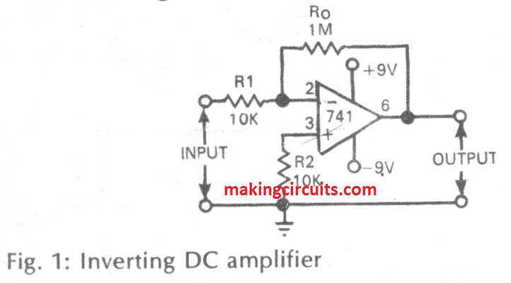

In the first Figure.1 we can see an inverting DC amplifier circuit with a gain of 100, which could be varied by adjusting the value of Ro.
Non-Inverting DC Amplifier
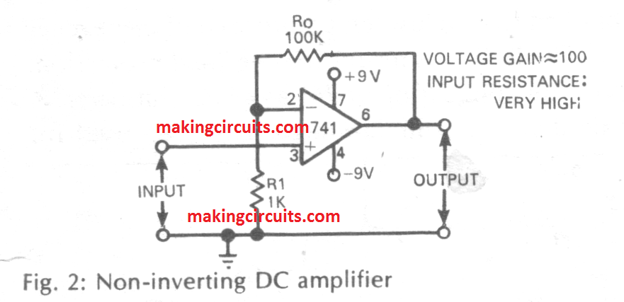

Figure 2 shows a non-inverting DC amplifier circuit using IC 741, with a set gain of around 100. Just like the above, here too the gain could be modified by varying the value of Ro. The input resistance of this IC 741 design is approximately 100M, and therefore it is very suitable for making buffer amplifier stage.
AC coupled inverting Amplifier
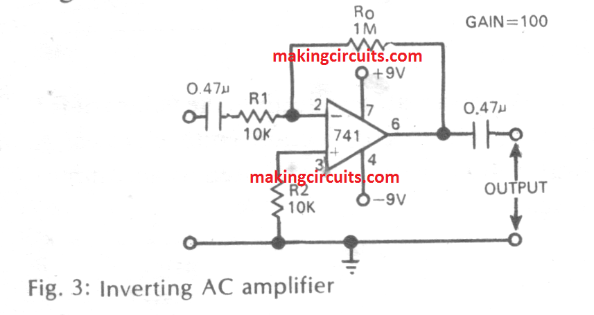

Figure.3 present an AC coupled inverting amplifier circuit configured with a gain of 100. It has been modified from the earlier DC inverting amplifier design, by including input and output coupling capacitors. For this design also the gain is adjustable by means of Ro value.
AC Coupled Non-Inverting Amplifier


Figure.4 brings us an AC coupled non-inverting amplifier circuit with a gain of 100. It is also similarly customized from the previous basic non-inverting amplifier design by introducing R2 with a corresponding coupling capacitors.
DC Buffer Amplifier (Voltage Follower)
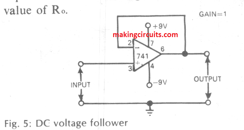

Figure.5 gives us a buffer amplifier design using a single IC 741. This design is featured with an extremely high input resistance and very low output resistance. The gain of th system can be assumed to be at 1 or unity, and the output is in phase with the input. In other words the output signal is produced by following the input signal, and hence it is also called opamp voltage follower.
AC Buffer Amplifier (Voltage Follower)
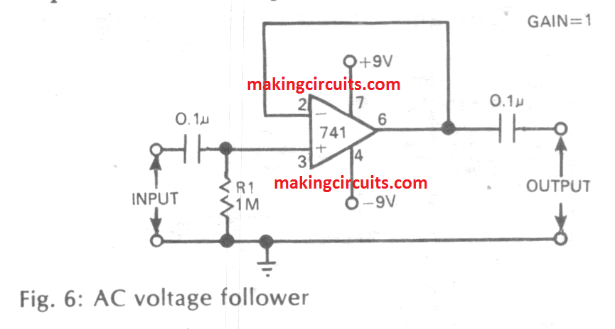

Figure.6 is similar to the above, but it is an AC voltage follower with unity gain, having very high input input impedance and very low output impedance.
Active Low Pass Filter
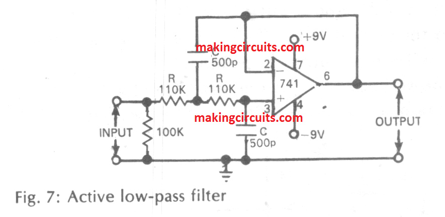

If you are looking for a simple active low pass filter , then this design of Figure.7 will work great for you. The circuit is configured to produce a cut-off frequency of around 2.2kHz, which could be effectively adjusted by changing the values of R and C.
Active High Pass Filter


Figure.8 is the opposite of the above design and is intended for getting a high pass filter using the opamp IC 741. The cut off frequency here is fixed at 2.8kHz which could be customized by changing the values of the resistor R and the capacitor C.
Small Power Amplifier
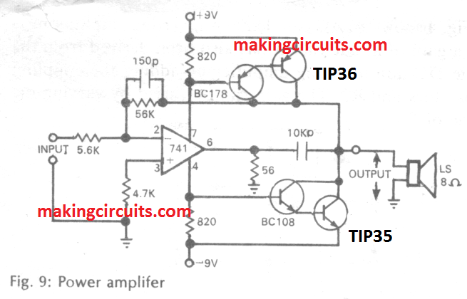

In Figure.9 we are able to see a small power amplifier based on the IC 741. This can be used as an intermediate driver amplifier in between a signal source and a big power amplifier. It features a distortion level of less than 0.5% with an output power of 3.5 watts. The input signal is expected to be around 170 millivolt. The bandwidth of the design is around 20 kHz.
Bass Treble Tone Control


IC 741 can be also effectively applied as an active bass, treble circuit as depicted in Figure.10. This design features a bass boost of 12 dB and a cut off of 11 dB at 100 Hz, while the treble boost can be achieved at 9 dB and a cut of of 10 dB at 10 kHz frequency, and reference frequency at 1 kHz. Te circuit exhibits a high input impedance and a low output impedance.
Precision Positive/Negative Voltage Reference


The next design in Figure.11 an Figure 12 shows the method of using the IC 741 with a zener diode to create a circuit of a precision voltage reference, having a very high stability. The first design shows how it may be designed to obtain a precision positive voltage reference and the second design indicates a negative precision reference.
Regulated Power Supply
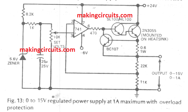

In the next figure.13 we find the IC 741 being used like a comparator/driver for configuring a simple yet highly regulated power supply circuit. The basic reference is set through a low coefficient zener diode of 5.6 V. The BJT BC107 is configured as an overload and short circuit protection for the power supply.
Simple Adjustable Range Voltmeter
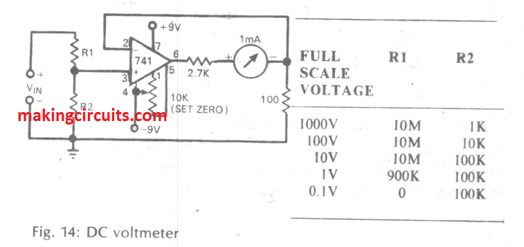

A good quality voltmeter and ammeter always becomes handy little circuit for all hobbyists. Figure.14 shows how his can be simply achieved by configuring a single IC 741 with a moving coil meter. The moving coil meter is supposed to have a full scale deflection of 1mA. The adjoining table shows the values of R1 and R2 that must be set for getting the range of full scale readings in response to the relevant voltage ranges.
Simple Ammeter with Adjustable Range
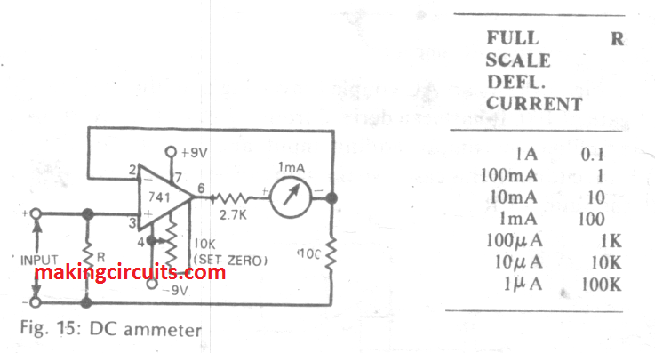

The above circuitry handles the voltage reading, and if you ae wondering how the same could be applied for measuring current, then the design shown in Figure.15 will fulfill your curiosity. Here, the IC 741 has been rigged as a simple ammeter using the same moving col meter having a range of 1mA full scale deflection. The adjoining table provides us with the various values for the resistor which corresponds to the full scale range of the meter for the relevant current or ampere ranges.
Simple Linear Ohmmeter


A nice little resistance meter can be built using a single IC 741 as shown the above Figure 16. Appropriate values of R are shown in the diagram itself for the respetive ranges of full scale deflections. A single pole 7 way rotary switch used is used for selecting between the values of the R depending on the resistor in question.
Many of the DMMs come with a non-linear scale for the measurement of the resistance values. The design shown here is built with a linear scale and features lowest full scale value of 1K to the highest value of 10 Meg. The circuit is quite simple.
Calibration is done by selecting the 10K range. Then the 1K preset is hooked up at the base of the BC107 transistor to achieve a precise 1 volt at its emitter.
After this a known resistor having a precise value of 10K is attached across the Rx terminals, and the 1 K preset is adjusted until the meter reads a full scale deflection. Once this is accomplished, the meter can be assumed to be calibrated and ready for use.
Simple AC Voltmeter
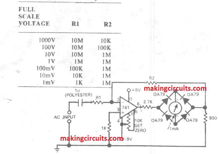

In Fig 17 above we can see a useful application of the IC 741 for measuring AC volts. The table alongside provides us with the values of R1 and R2 for the various respective full-scale deflection ranges of the AC voltages.
a double pole 7 way good quality rotary switch may be incorporated for enabling all the ranges within the system.
The capacitor at the input side of the circuit must be strictly a non-polar type of capacitor.
Simple Door Bell
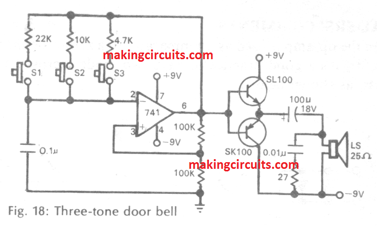

The above fig 18 indicaes how simply an IC 741, in association with a PNP-NPN BJT pair could be employed to form a door bell having 3 unique musical tones. The 3 push buttons are given for actuating the bell could be installed across may be 3 different doors. Eack of these switches when pressed would produce the relevant unique tone enabling the owner to know which door bell was pressed and which door needs to be attended.
Simple Timer Circuit
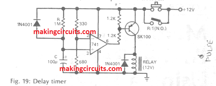

In Fig 19 above we can see a timer circuit application using the IC 741. The timer is energized as soon as the push button is pressed which in turn activates a relay and the load which may be attached with the relay contacts.
Once the relay is activated, the N/O contacts is used for latching the circuit through itself and also providing the power to the connected load.
The relay and circuit remain activated for a time period dependent on the values of the R and C.
With the indicated values of R and C, the ON time delay for the relay could be assumed to be around 100 seconds.
The diode across R makes sure that the capacitor C quickly discharges once the relay is switched OFF so that the circuit becomes reset and in the standby mode for the next delay cycle at an earliest.
Simple Light Activated Switch


The figure.20 above shows a simple yet accurate self latching light activated switch circuit. The LDR which is a light sensitive device presents a low resistance in the presence of ambient light, and a high resistance when it is darker.
The preset R is adjusted such that its value becomes approximately equal to the value of the LDR's resistance during normal light conditions.
This makes sure that with normal ambient light the relay stays switch OFF, and becomes switched ON as soon as the light level on the LDR goes drops below a threshold level. The relay contacts now latches the circuit so that it locks ON permanently until the circuit is manually switched OFF by the owner.
The latching feature is not compulsory and could be eliminated, and the relay could be instead connected with a load for such as a lamp for illuminating it during darkness and turning the circuit into a darkness activated lamp.