Managing high current heaters rated as much as 2000 watt needs strict specs with the managing unit for safe and useful execution of the meant procedures. With the advent of sophisticated snubber-less Triacs and Diacs producing heater controllers at substantial watt levels is now fairly simpler these days.
Below we research a straightforward yet completely appropriate configuration which can be used to make a high current 2000 watts heater controller circuit.
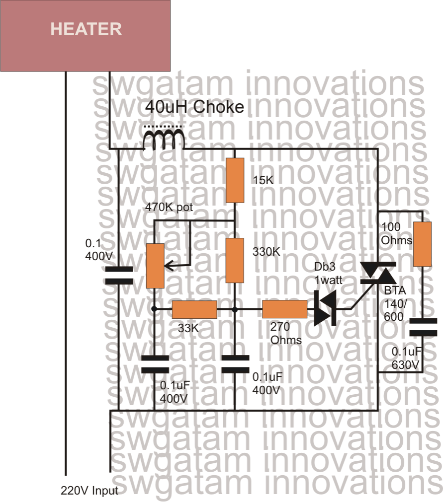
Let's recognize the presented circuit diagram with the following points:
The set up of the circuit is fairly regular as the the wiring is extremely much like the ones which can be usually utilized in normal light dimmer switch circuits.
The normal triac and diac set up may be seen for applying the simple switching of the triac.
The diac is a device which switches current across itself only after a particular chosen potential difference is attained across it.
The following network resistors and capacitors related to the diac are selected such that they permit the diac to fire only provided that the sine curve stays below a specific voltage level.
The moment the sine curve exceeds the above specific voltage level, the diac quits carrying out and the triac is turned OFF.
Given that the load or the heater in this instance is linked in series with the triac, the load also switches OFF and ON in keeping with the triac.
The above conduction of the triac only for a specified section of the input sine voltage curve, leads to an output across the triac which includes the AC chopped into smaller sections, creating the overall RMS of the resultant drop to a lower value, based upon the values of the relevant resistors and capacitors around the diac.
The pot which can be demonstrated in the figure is utilized for handling the heater element which is linked to the above described process. The greater the opposition, the longer it requires or the capacitor to charge and discharge whih in turn prolongs the firing of the diac/triac pair.
This prolongation will keep the triac and the load switched OFF for a longer section of the AC sine curve which results in the same way lower average voltage to the heater, and the heater temperature continues to be at the cooler side.
On the other hand when the pot is modified toward to generate a lower resistance, the capacitor charge and discharge at a faster rate producing the above cycle rapid which often the average switching period of the triac at the higher side, resulting a higher average voltage to the heater. The heater currently produces more heat due to the improved average voltage created across it via the triac.
WARNING: CIRCUIT IS NOT ISOLATED FROM MAINS AC. BE EXTREMELY CAREFUL WHILE TESTING THE CIRCUIT IN UNCOVERED POSITION. IT IS RECOMMENDED ONLY FOR THE EXPERTS.