

This economical power inverter was created to produce as much as 250 watts for powering all line controlled devices with a small percentage of the commercially constructed products.
The inverter explained in this article has been accustomed to power flood lights, soldering irons (both resistance and inductor models), fans, tvs, and personal computers. It has actually powered an air pump for the author's application.
The inverter will operate just about any system which works on 120 volts AC. Several motor-driven gadgets will not likely work effectively, nevertheless a adjustable -speed drill may perform, but only with a single speed. Fans and other forms of purely inductive loads manage to operate at about 2/3 standard speed using the inverter. Synchronous motors may function at standard speed but will be a bit "noisy."
The MOSFETs
MOSFET devices have gotten handier during the last several years and, simultaneously, the costs for them have significantly come down. Practically nothing can be compared to MOSFET's capability of working with logic signals, and for the convenience through which it may function in parallel with identical devices without any additional ingredients.
To put MOSFETs in parallel what you just have to do is connect the source, drain, gate terminals together. Once they become heated, FET's display a positive temperature characteristic, which implies as the temperature rises, so will the resistance; because the resistance rises, the current through the MOSFET is actually reduced.
This enables FET's auto heat controlled. MOSFET's are increasingly being manufactured with power ratings that could typically help to make parallel functioning needless. The specifications for the IRFZ30's which are found in this project are cool: they are able to deal with a 30 amp load with 50 volts over the source drain terminals and 75 watt power dissipation, all these in a TO-220AB package.
Circuit Duagram

How it Works
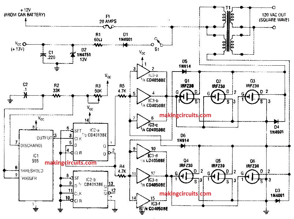
Figure 1 displays the schematic of the inverter. A 555 timer, ICI, together with R3.. R2, and C2, produces a 120 -Hz (±-2 Hz) signal, as established through the potentiometer R3 adjustments.
The output from IC1 at pin 3 is linked to the CLOCK input of a CD40I3BE which is a dual D-type flip-flop. IC2 -a, is configured to split the input frequency by 2; which results in the 60 Hz clocking for the MOSFET string (Q1-Q6). The output from flip-flop IC2-a at pin 1 carries a 50% duty cycle, that is essential for the output transformer.
The flip-flop additionally offers an inverted output (Q_, pin 2), which in turn spares us from the need to include extra parts to invert the Q output. The 2nd part of IC2 (IC2-b) is not really employed.
Thus every one of its input pins tend to be grounded. The Q and Q_ outputs from IC2-a are each connected via R5 and R4, to 3 inputs of IC3, a CMOS CD4050BE hex buffer. Each category of 3 buffer outputs runs a single group of MOSFET's in the power stage.
The inputs towards the buffers are likewise managed by D5 and D6, that are coupled to the MOSFETs drains, in order that the string which is turned ON basically are able to control the drivers of the other string.
When one side is switched on and its drain reaches ground level, the other section is not able to switch on since the input to the buffer for that particular string is also being connected at ground level.
This continues to be like that until the controlling string has totally switched off and the drain voltage proceeded to go over around 6 volts. This is important since the turn-off time for a MOSFET is more compared to its turn OFF time.
In case the diodes were being removed, the two arrays of FET's could be switched on at the same time in the course of each transition. This results in huge surges on the battery, the appliances linked with the output of the inverter, and also to the MOSFET's themselves.
The FET string could be designed as large or as small as your own applica tion demands. This articles author required a minimum of 250 watts, and made use of a couple of IRFZ30's in parallel for every single string.
On the other hand, to try out it risk-free, make use of 3 in parallel (or however many you would like) for every string as we have demonstrated in the schematic. Diodes D4 and D3 blunt of inductive spikes coming from the transformer winding that might otherwise lead to overheating and early transistor malfunction.
Power supply enhancing circuitry (D1, Rl, D2, and C1) gets rid of surges, overloads, along with other disturbance from a car's 12 -volt supply. Although the 555 are designed for up to a 15 volt supply, power supply spikes can definitely ruin it.
In case the transformer you employ includes a center tap, the center tap should be attached to the 12 volt line and the two 12 volt windings should be hooked up to the drains of their individual driving transistors.
The author made use of a Jefferson buck/boost transformer which typically accustomed to decrease or boost the line voltage for AC equipment. If you want to obtain a transformer, feel free to use any center -tap 24 -volt or double -winding 12 -volt transformer. It is essential to make use of a transformer that may give you the volume of current that your program demands.
Construction
A few of the parts can be assembled over a compact PC board, for which we have offered the track design. The components positioning plans is demonstrated in Fig. 2.

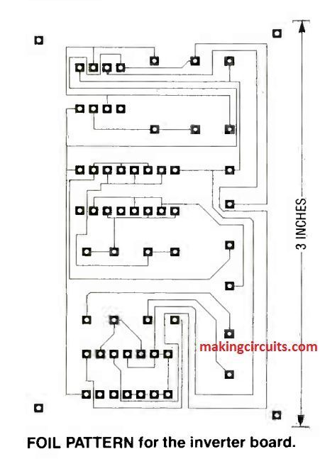
We advise that you make use of sockets for the IC's. Following soldering all elements on the board, switch ON 12 volts and read the frequency on the pads that are marked as J4 and J2. Fine-tune R3 for a reading of 60 Hz (for 120V) or 50 Hz (for 220V), and ensure the voltage is rather in close proximity to 1/2 of the supply voltage on each pad.
This lets you know that your particular duty cycle is 50%. At this point attach the remainder of the parts. The tiny number of off-board parts may be installed on a terminal strip.
Having said that, make sure to install the MOSFET's over a heatsink. In the event the heatsink is at ground potential make sure to insulate (with MICA) each of the MOSFET's from it.
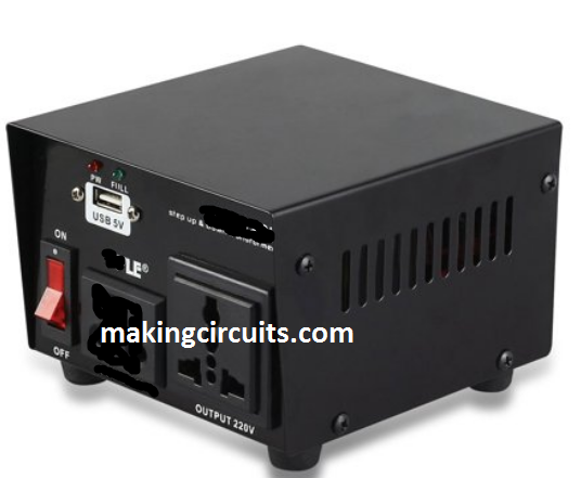
A regular AC outlet had been installed on the front panel of the unit. The prototype was set up within an good old, durable sheet metal cabinet, nevertheless feel free to use anything you have got available.

How to Operate
To be able to run the unit, connect the supply power into input socket, switch on the power switch, and start up the appliance which is attached to the inverter. While you are not using the inverter, you should definitely switch it off, because the transformer may pull about 2 amps even without any load. Which will deplete your car battery pretty quickly!


Parts List
All resistors are 1/4 -watt, 5%, unless otherwise noted.
R1-60 ohms, 1 watt, 10%
R2-33,000 ohms
R3-50,000 ohms, potentiometer
R4, R5-4700 ohms
Capacitors
C1-220 µF, 35 volts, electrolytic
C2-0.1 µF, 50 volts, ceramic disk
Semiconductors
!C1-LM555 timer
)C2-CD4013BE CMOS dual D - type flip-flop
IC3-CD4050BE CMOS hex buffer
D1, D3, D4 -1N4001 diode
02-1N4751 13 -volt Zener diode
D5, D6 -1N914 diode
Q1-Q6-IRFZ30 30 -amp, 60 -volt FET or any other equivalent