

The 3 in 1 tester circuit explained in the following article is actually a combination of signal injector, signal tracer, and logic probe, which allows the user to accurately test and troubleshoot any electronic circuit or circuit PCB fault, quickly.
How the Circuit Works
This 3-in-1 circuit fault tester circuit is developed around a 4049-hex inverter/buffer. In figure below, you can spot two inverters (from a 6-inverter unit) which are used in a dual-frequency signal-injector circuit.


Another inverter is utilized as a logic problem and the rest of them are assigned as a sensitive dual-input, audio signal tracer.
Signal Injector
The signal-injector section of the 3-in-1 set comprises of gates U1-a and U1-b. These gates are set as a two-frequency, pulse-generator circuit.
Normally, the generator’s output frequency is about 10 kHz. However, once S2 is closed, there is a drop and the signal become close to 100 Hz.
For higher frequencies, you must bring down the values of C1 and C2. Inversely, you have o increase the capacitor values to obtain lower frequencies. For this circuit, both AC and DC outputs are supplied.
Logic Probe
The logic-probe section of the circuit consists of U1-c and a few LEDs which function to indicate the “high” or “low” state by switching on an LED. Once a logic high is supplied to the input of U1-c, the output of the inverter switches to low.
This low output reverse biases LED2 so it stays off. At the same time, the low output from U1-c forward biases LED1 which causes it to turn on.
However, when a logic low is set at U1-c’s input the whole situation converses, where LED2 becomes lit and LED1 turns off. Resistors R2 and R3 constrict the flow of current from the LEDs to around 10 mA.
Signal Tracer
The audio-signal tracer portion of this circuit consists of U1’s three remaining inverters (U1-d to U1-f) which are set ad linear audio-amplifier that is utilised to enhance the input signal by a factor of 10 or 100.
The boosted output signal supplies a miniature piezo element for sound detection.
Parts List

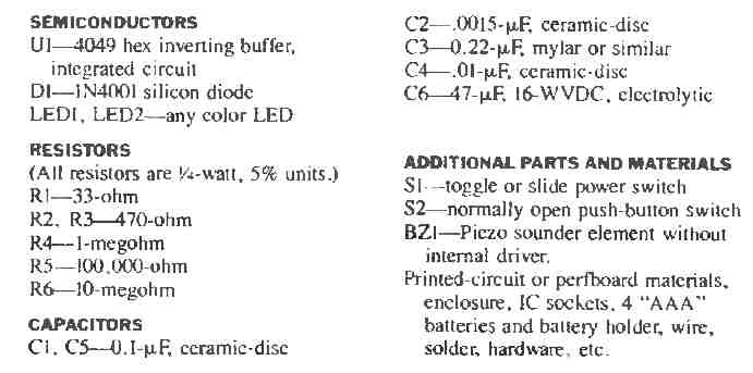
The total cost for this 3 in 1 tester circuit parts is very cheap (less than five dollars). Furthermore, you can effortlessly construct it on a perfboard or PCB, depending on your choice.
What is most important is keeping the leads short and a tidy circuit schematic.