

This posts tells you how to make a simple 3 state battery charge level indicator circuit 3 LEDs and a couple of opamps
Circuit Description
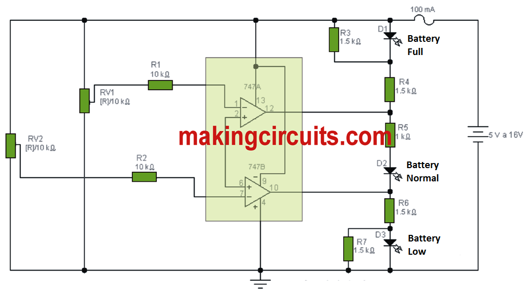
To find out the condition of charge in which a battery is positioned, this circuit has been developed according to a window comparator using low consumption operational amplifiers. The circuit utilizes three LEDs (D1, D2 and D3), attached in between their outputs, to indicate one among three probable states in the battery: full charge, moderate charge and discharged.
The circuit is driven via a 100mA fuse, despite the fact that its consumption is merely around 20mA, it is provided with straight to the terminals of the battery that it may monitor and it can achieve this task with batteries involving 6 and 12V.
Through the variable resistors RV1 and RV2, the voltage levels V1 and V2 are tweaked that on which the red and yellow, and yellow and green LEDs turn on or off.
To give an example, think about the situation of a 12V car battery, using V1 equal to 12V and V2 corresponding to 11V; in this instance, the green LED lights up using 12V or maybe more, the red lights at a voltage lower than or of about 11V, and the yellow continues to be illuminated in between both of these voltages.

Tested Prototype Image


Battery Charge/Discharge Indicator Circuit
This battery charge/discharge indicator circuit is designed to keep track of car battery voltage.


It varies from all other circuits in this it provides indication of the minimal supply voltage along with low or high voltage.

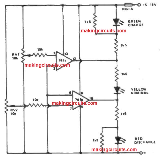
This would make it especially a good choice for suggesting deviation of the supply voltage through the nominal.
Three LEDs are employed - red, yellow and green. Yellow signifies the minimal voltage and red and green signify low and high values correspondingly.
RV1 and RV2 modify the point from which the red/yellow and yellow/ green LEDs are on or off.
As a result, a vast supply voltage could be examined. The prototype is actually mounted in a car and place in order that the red LED turns on at 11V 7 and also the green LED at 1 2V8.
The yellow LED illuminates between these values.
Battery Monitor Circuit Using Zener Diodes and LEDs
Here is a concept for simple 3 LED battery monitor circuit, by means of a voltage monitor for 1 2V supplies, implying the two over or under tolerance voltages.
Employing three LED's the individual can observe right away whether power is on, over - voltage or under -voltage.

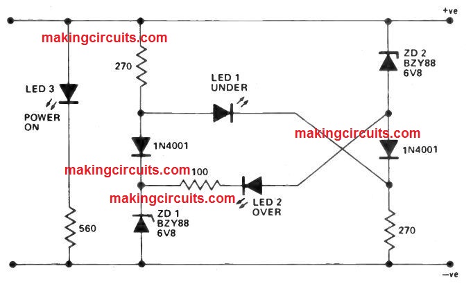
This can be accomplished using a balanced bridge which employs zener diodes ZD1 and ZD2 in the bridge's opposite arms and back-to-back LEDs between the center of the bridge arms, in case the input voltage is not going to surpass the two zener breakdown voltages (2 x 6V8= 1 3V6) LED 1 lights however above 13V6 LED1 gets reverse biased and stays off.
Once the battery voltage increases towards the extent that at the junction of ZD2, it surpasses the zener voltage of ZD1 , and also the LED voltage of 1.6V, then LED2 is switched on, with resistor 100R restricting the current from the LED. Notice complete drain of unit is around 50 mA.