

You will discover an incredible variety of VW Beetles and Fords on the streets which continue to work on a 6 V battery.
In such vehicles (and motorcycles) one can find often difficulties while making an attempt to install a modern car radio as they require a power supply of at least 10.7 V.
One option would be to include a 6 to 12 V converter from this type identified in this article.
This particular easy converter offers an output of around 700 mA and is comparatively cheap to build The two of these properties - simple and easily affordable - arise through the understanding of the circuit which consists of two integrated audio power amplifiers and does not need a transformer.
Circuit Description
The first amplifier, IC1, performs as an astable power multivibrator.
The frequency of oscillation depends upon the importance of capacitor C3 and is also somewhere around 4 kHz without any load and maximally 6 kHz whenever a load is used.
The output signal of a second amplifier, IC2, is equivalent to that particular of the first, albeit 180 degrees from level.

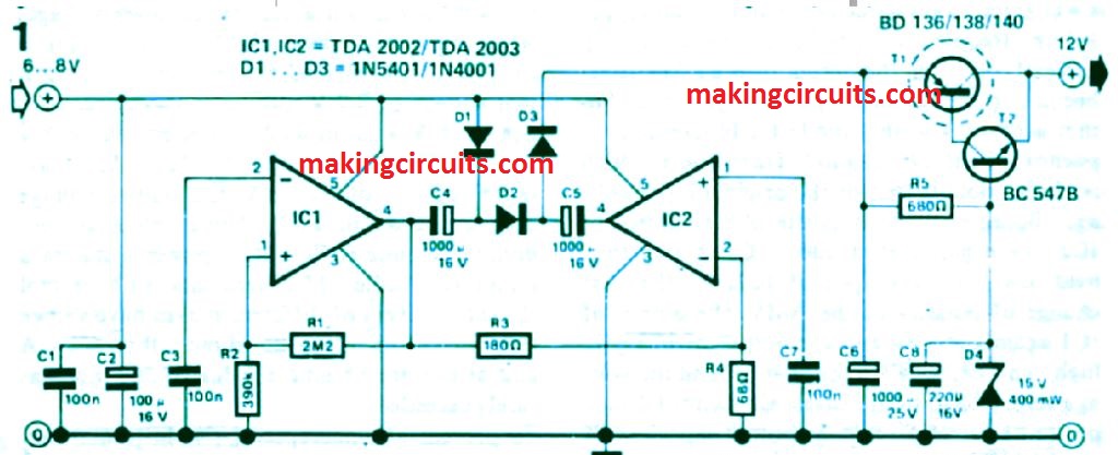
When the output voltage of IC1 is low, capacitor C4 charges up via diode Dl to nearly full supply voltage (lowered somewhat through the potential fall around Dl).
Once the output of the AMV (IC1) will become positive, the output voltage is added to that across C4 so that diode Dl blocks and capacitor C5 charges via diode D2 to a level which can be practically twice that of the original input voltage.
Due to opposite phase control of IC2, the negative electrode of C5 is until then held low via the output of IC2.
At the next change of polarity of the AMV, the output of IC1 yet again goes low and the output of IC2 will go high.
This specific leads to C4 to generally be charged and the voltage throughout C5 to be increased.
Capacitor C5 then passes its potential on to the output capacitor C6 via diode D3.
In this theory, as a result, the ultimate result of the circuit is to treble the input voltage, however in process C6 which will simply achieve a considerably lower voltage, which usually depends upon the load.
Measurements taken says a 6 V lead-acid battery with a minimal voltage of 7.2 V, generated an output voltage of 18 V without any load attached, although with a load of 750 mA this slipped to 12 V.
At an 'average ' current of 400 mA, the output voltage amounts to about 14 V.
These types of values are definitely pretty satisfactory to power a normal mono car radio.
Measurements with a number of related receivers of various makes have demonstrated that non-e of them consumed more than 500 mA and at average volume a value of 300 mA was almost never exceeded.
In order to avoid an undesirable rise in power usage when attached to a low impedance load, the converter receives however limiter phase comprising a 15 V zener diode and a complementary Darlington circuit (transistors Tl and T2).
How to Set Up
This set up limits the utmost voltage to about 14,2 V.
Simultaneously, capacitor C8 coupled to the two transistors diminished the ripple of the output voltage to lower than 50 mV below full load circumstances.
In the course of practical demos no a result of the oscillating frequency of the converter on the quality of radio reception was observed The printed circuit board for the converter is demonstrated in figure 2.

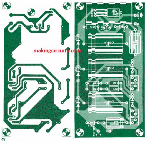
Because of its small size, construction of the circuit ought not to create any kind of difficulties.
Both IC amplifiers and transistor Tl could be maintained adequately cool if these types of elements are positioned (with mica cleaners) on a common heatsink across the longest side of the board.
The heatsink must be as significant as the board itself and should be fitted at 90 degrees to the board to assure the best possible heat transfer.
Both IC amplifiers consist of built-in safety circuitry towards short circuits and thermal overload, in order that the most severe do not need to be terrifying if the unit is pass through overload or overheating.
Often the TDA 2002 or the TSA 2003 can be utilized for the amplifiers.
The TDA 2003 has got the edge on the 2002 due to a few enhanced features. Exactly the same is valid for the diodes; the 3 A diodes (1N5401) are best suitable simply because less voltage is slipped around them.
When 1N4001 sorts are utilized, a loss in output voltage of 0.5 V to 1 V can be expected.
If the values of capacitors C4, C5 and C6 are enhanced to 200 m F, the maximum output current is brought up by about 100 mA.
For even higher output currents, two converters could be attached in parallel.
It's possible that, the limiting phase (R5, C8, D4, Tl and T2) is overlooked through the second board and a link made between the two positive electrodes of the two C6s.
Transistor Tl can then be among the subsequent kinds; BD 236, BD 238, BD 204, BD 288 or BD 438.
The utmost current which can be acquired by linking two converters in parallel is virtually doubled to about 1.3 A, as a result stereo or cassette radios could be set up in 6 V cars without difficulty
Parts List

