Direct Current or D.C. is a type of electric current which moves through an electrical circuit in a single direction only, rendering it a “Uni-directional” power source.
Typically, DC currents and voltages are manufactured by power supplies, batteries, dynamos and solar cells to mention just a few. A DC or direct current carries a predetermined, permanent dimensions (amplitude) and a precise direction related to it. Take for example, a +12V may signify 12 volts within the positive path, or -5V may signify 5 volts within the fixed negative path.
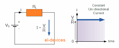
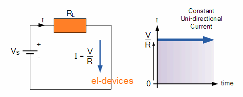
All of us understand that DC power supplies can normally never modify their value in terms of period, these have a consistent value streaming in a constant stable path. Put simply, DC retains exactly the same value constantly and unidirectionally. DC supplies normally will never change its polarity or direction, unless of course the input connections are physically reversed. A good example of a basic DC or direct current circuit is demonstrated underneath.
DC Circuit and Waveform
An alternating function or AC Waveform alternatively is understood to be one which deviates in both magnitude and direction in approximately a consistent pattern with time, turning it into a “Bi-directional” waveform. An AC function could symbolize both a power source or a transmission source carrying the shape of an AC waveform, typically pursuing a mathematical sinusoid defined as: A(t) = Amax*sin(2pƒt).
The expression AC or to provide it its total outline of Alternating Current, usually pertains to a time-varying waveform with the most popular called a Sinusoid also recognized as a Sinusoidal Waveform. Sinusoidal waveforms are more commonly named by their brief terminology Sine Waves. Sine waves are undoubtedly the most crucial forms of AC waveform found in electrical engineering.
The waveform shape acquired by mapping the instantaneous ordinate values of either voltage or current with respect to time is known as an AC Waveform. An AC waveform will be continuously modifying its polarity each half cycle alternating across a positive highest value and a negative highest value correspondingly in relation to time. A typical illustration of this could be our home mains voltage supply specified within 120V or 220V as per country specs..
This implies that the AC Waveform is actually a “time-dependent signal” having the most prevalent type of time-dependant signal which is the Periodic Waveform. The periodic or AC waveform becomes the end product of a spinning power generator. Typically, the wave pattern of any periodic waveform could be produced through a fundamental frequency and superimposing it together with harmonic signals with changing frequencies and amplitudes, we may learn more about it in another tutorial.
Alternating power can be impossible to be stored in batteries unlike like direct current (DC) which can be stored in batteries by charging them., it is less difficult and less expensive to produce AC through alternators or waveform generators whenever it is necessary. The variety and model of an AC waveform is determined by the power generator or gadget generating them, however all AC waveforms incorporate a zero voltage range which splits the waveform into a pair of symmetrical halves. The primary attributes of an AC Waveform are identified as:
AC Waveform Characteristics
• The Period, (T) may be defined as
the time period in seconds which the waveform requires to replicate itself through beginning to end. This could likewise be referred to as Periodic Time of the waveform with regard to sine waves, or the Pulse Width with regard to square waves.
• The Frequency, (ƒ) may be defined as
the number of periods the waveform repeats itself within a time frame of one second. Frequency is the reciprocal of the time period, ( ƒ = 1/T ) having the unit of frequency as Hertz, (Hz).
• The Amplitude (A) may be defined as the magnitude or depth of the signal waveform tested in volts or amps.
Within our article about Waveforms ,we researched various kinds of waveforms and declared “Waveforms are essentially a visible manifestation of the varying of a voltage or current plotted with refernce to a time base”. Typically, with regard to AC waveforms this horizontal base line signifies a zero reference of either voltage or current. Any portion of an AC type waveform situated over a horizontal zero axis symbolizes a voltage or current moving in a single direction or path.
Identically, any portion of the waveform situated under the horizontal zero axis symbolizes a voltage or current moving in the reverse direction compared to the waveform situated above the zero line . Commonly with regard to sinusoidal AC waveforms the appearance of the waveform over the zero axis is equivalent to the appearance under the zero line. On the other hand, for many non-power AC signals which includes sound waveforms this may not be always true in such cases.
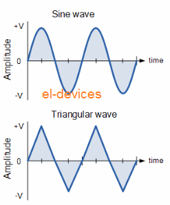
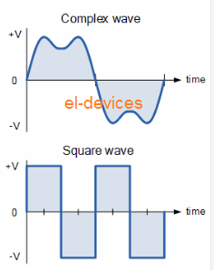
The most prevalent periodic signal waveforms applied in Electrical and Electronic Engineering are the Sinusoidal Waveforms. Having said that, an alternating AC waveform might not continually carry the consistent shape centered around the trigonometric sine or cosine function. AC waveforms may also acquire the appearance of possibly Complex Waves, Square Waves or Triangular Waves as proven underneath.
Types of Periodic Waveform
The time period consumed by an AC Waveform to accomplish a single complete pattern starting from its positive half to its negative half and returning back to its zero baseline is known as a Cycle and one full cycle is made up of each a positive half-cycle and a negative half-cycle.
The moment consumed by the waveform to accomplish a single complete cycle is known as the Periodic Time of the waveform, and it is expressed as the symbol “T”.
The quantity of full cycles which are generated in one second time frame (cycles/second) is known as the Frequency, with symbol ƒ of the alternating waveform. Frequency is calculated and expressed in Hertz, ( Hz ) given its name after the German physicist Heinrich Hertz.
Now you observe that a relationship is available between cycles (oscillations), periodic time and frequency (cycles per second), hence when there are ƒ amount of cycles in a single second, each specific cycle ought to take 1/ƒ seconds to accomplish.
Relationship Between Frequency and Periodic Time
or
AC Waveform Example No1
1. What should be the periodic time of a 50Hz waveform and 2. Calculate the frequency of an AC waveform carrying a periodic time of 10mS.
1).
Periodic Time, (T) = 1/f = 1/50 = 0.02 secs or 20ms
2).
Frequency, (f) = 1/T = 1 / 10 x 10-3
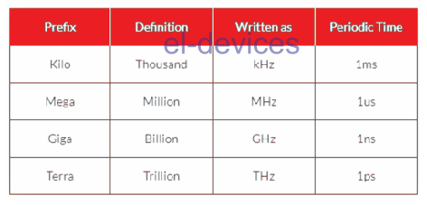
Frequency was previously depicted in “cycles per second” abbreviated to “cps”, these days it is more frequently described in unit named “Hertz”. For a home-based mains supply the frequency is going to be either 50Hz or 60Hz based upon the country specification and is set with refernce to the rotational frequency of the hydro-generator. However one hertz can be an extremely tiny unit therefore prefixes are widely-used which signify the sequence of dimensions of the waveform at greater frequencies for example kHz, MHz and even GHz.
Definition of Frequency Prefixes
Amplitude of an AC Waveform
In addition to the periodic time or the frequency of the alternating quantity, another essential parameter of the AC waveform is usually the Amplitude, generally known by its Highest or Peak value symbolized with the terminology, Vmax for voltage or Imax for current.
The peak value is the highest value of both voltage or current which the waveform tends to attain in the course of each half cycle with reference to the zero baseline. In contrast to a DC voltage or current that has a stable status that may be calculated or determined employing Ohm’s Law, an alternating magnitude is continuously changing its value with time.
For pure sinusoidal waveforms this peak value will invariably be the same for both half cycles ( +Vm = -Vm ) however for non-sinusoidal or intricate waveforms the highest peak value could be completely different for each half cycle. Occasionally, alternating waveforms are granted a peak-to-peak, Vp-p value which is merely the length or the sum in voltage involving the maximum peak value, +Vmax and the minimum peak value, -Vmax throughout one full cycle.
The Average Value of an AC Waveform
For a continuous DC the mean or average value will constantly be equivalent to its highest peak value since a DC voltage is constant. This particular average value is only going to alter in case the duty cycle of the DC voltage changes. In a pure sine wave when the average value is computed within the full cycle, the average value might be corresponding to zero since the positive and negative halves will tend to cancel or terminate each other out. Therefore the average or mean value of an AC waveform is worked out or tested specifically within a half cycle as demonstrated below.
Average Value of a Non-sinusoidal Waveform
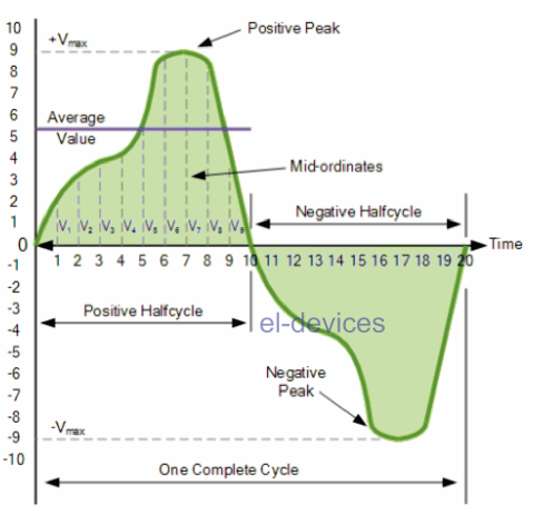
To obtain the average value of the waveform it may be required to calculate the area below the waveform utilizing the mid-ordinate rule, trapezoidal principle or perhaps the Simpson’s rule which are typically noticed in mathematics. The rough area below just about any unpredictable waveform may be quickly determined by applying the mid-ordinate rule.
The zero axis base line will be split up into numerous equivalent pieces and in our basic example above this value had been nine, ( V1 to V9 ). Higher the number of ordinate lines sketched better the accuracy will be for the ultimate average or mean value. The average value would be the sum of all the instantaneous values added with each other and subsequently divided with the total quantity. This can be expressed as.
Average Value of an AC Waveform
V(average) = V1 + V2+ V3+ V4 + ...+ Vn / n
Where: n equals the actual number of mid-ordinates used.
With regard to a pure sinusoidal waveform this particular average or mean value will be always = 0.637*Vmax and this relationship additionally continues to be true for average values of current.
The RMS Value of an AC Waveform
The average value of an AC waveform that all of us computed above as 0.637*Vmax will NOT be the identical value we might apply in case of a DC supply. The reason being as opposed to a DC supply which is constant and has a permanent value, an AC waveform is continually modifying as time passes and possesses absolutely no fixed value. Therefore the comparable value for an alternating current technique that delivers the identical quantity of electrical power to a load like a DC equivalent circuit is referred to as the “effective value”.
The effective value of a sine wave creates the identical I2*R warming impact inside a load as may be expected when a constant DC supply was used for that load. The effective value of a sine wave is frequently referred to as the Root Mean Squared or simply RMS value and calculated as the square root of the mean (average) of the square of the voltage or current.
Meaning Vrms or Irms may be presented as the square root of the average of the sum of all the squared mid-ordinate values of the sine wave. The RMS value for just about any AC waveform is available through the below shown modified average value formula as demonstrated.
RMS Value of an AC Waveform
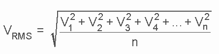
Where: n equals the number of mid-ordinates.
With regard to a pure sinusoidal waveform this particular effective or R.M.S. value will be always = 1/v2*Vmax or 0.707*Vmax and this relationship can be also applied for RMS values of current. The RMS value with regard to a sinusoidal waveform will be always higher than the average value except for a rectangular waveform. In such cases the heating up influence continues to be consistent hence the average and the RMS values also remains identical.
One closing opinion regarding R.M.S. values. The majority of multimeters, both digital or analogue unless otherwise reported exclusively determine the R.M.S. values of voltage and current and not necessarily the average. Hence when utilizing a multimeter with a DC system the display may be equivalent to I = V/R and in case of an alternating current system the measurement will probably be equivalent to Irms = Vrms/R.
Additionally, apart from average power calculations, while calculating RMS or peak voltages, make sure to use only VRMS to get IRMS values, or peak voltage, use Vp to obtain peak current, Ip values. Never combine these with each other as Average, RMS or Peak values of a sine wave tend to be entirely different and your results could be utterly wrong.
Form Factor and Crest Factor
Although not common these days, both Form Factor and Crest Factor could be employed to obtain details regarding the genuine shape of the AC waveform. Form Factor tells you regarding ratio between the average value and the RMS value and may be expressed as.
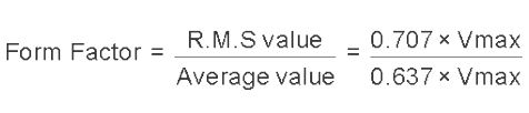
For a pure sinusoidal waveform the Form Factor will be always = to 1.11. Crest Factor gives you the ratio between the R.M.S. value and the Peak value of the waveform and may be expressed as.
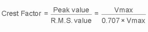
Considering a pure sinusoidal waveform the Crest Factor will be always = 1.414.
AC Waveform Example No2
A sinusoidal alternating current carrying 6 amps is applied across a resistance of 40O. Calculate the average voltage and the peak voltage of the supply.
The R.M.S. Voltage value is calculated as:
Vrms = I x R = 6 x 40 = 240
The Average Voltage value is calculated as:
Form Factor = V(rms) / V(average)
? V(average) = Vrms / Form Factor = 240 / 1.11 = 216.2 volts
The Peak Voltage value is calculated as:
Peak Voltage = RMS x 1.414
? 240 x 1.414 = 339.4 volts
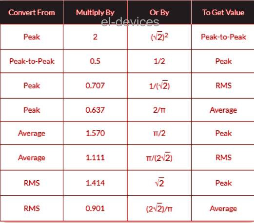
The utilization and computation of Average, R.M.S, Form factor and Crest Factor can additionally be applied on almost any periodic waveform such as Triangular, Square, Sawtoothed or any other unpredictable or complicated voltage/current waveform dimension. Conversion process between the various sinusoidal quantities can often be puzzling therefore the following table helps to provide a hassle-free method of converting one sine wave value to another.
Sinusoidal Waveform Conversion Table