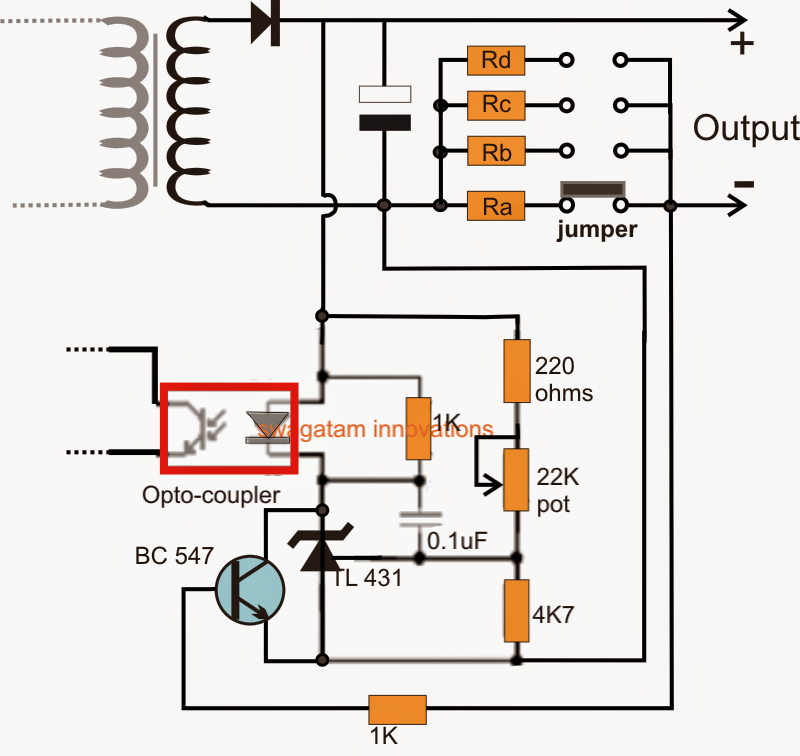
This post explains a technique during which any ready made SMPS could be changed into a variable current smps circuit making use of just a few external jumper links.
In one of the prior posts we figured out to produce a variable voltage SMPS circuit by making use of an easy shunt regulators stage, in the present hack also we implement the same circuit stage for developing a variable current output function.
In the above associated post we talked about how an opto coupler performed a vital role in delivering the significant constant output feature for virtually every SMPS.
The feature of the opto coupler could be noticed with the following brief clarification:
How the Circuit Works
The opto coupler shows an inbuilt LED/photo-transistor circuitry, this device is integrated with the SMPS outputs step such that when the output tends to overcome the dangerous threshold, the LED inside the opto lights up forcing the phototransistor to carry out.
The photo-transistor on the other hand is configured across a very sensitive "shut down" point of the SMPS driver stage wherein the conduction of the photo-transistor pushes the input stage to shut down.
The above circumstance causes the SMPS output to also at the same time disconnect, in spite of this the instant this switching initiates, it corrects and renews the output to the safe zone and the LED inside the opto deactivates which once again switches ON the input stage of the SMPS.
This operation keeps on cycling swiftly from On to OFF and vice versa guaranteeing a persisting voltage at the output.
How to get an Adjustable Current SMPS Circuit
With the intention to gain a current control feature inside any SMPS we once more search for the help of the opto coupler.
We apply a simple modification utilizing a BC547 transistor configuration as proven below:
Adjustable Current SMPS Circuit
Discussing the above design we get a definite idea relating to the way to adjust or make a variable current SMPS driver circuit.
The opto coupler (suggested by red square) will likely be contained by default for all SMPS devices, and so long as the TL431 is not present then we could possibly have to configure the overall configuration involved with opto coupler LED.
If the TL431 stage is actually a part of the SMPS circuit, as a result we only have to examine developing the BC547 stage which evolves into entirely liable for the suggested current control of the circuit.
The BC547 can be visible linked with its collector/emitter across the TL431 IC's cathode/anode, and the base of BC547 can be visible linked with the output (-) of the SMPS via a couple of selectable resistors Ra, Rb, Rc, Rd.
These kinds of resistors being in between the base and emitter of the BC547 transistor activate performing like current sensors for the circuit.
However these are correctly measured such that by shifting the jumper connection across the related contacts, several current limits are established in the range.
When the current tends to increase beyond the set threshold as determined by the values of the matching resistors, a potential difference is created across the base/emitter of the BC547 which evolves into ample to activate the transistor, shorting the TL431 IC between the opto LEd and ground.
The above measures promptly lights up the LED of the opto, submitting a "fault" signal to the input side of the SMPS via the opto's in-built photo transistor.
The condition right away makes an effort to carry out a shut down across the output side which unfortunately quits the BC547 from executing and the condition fluctuates from ON to OFF and ON swiftly making sure that the current certainly not is more than the predetermined threshold.
The resistors Ra...Rd could be measured through the use of the following formula:
R = 0.7/cut-of current threshold
As an illustration if assume we need to connect an LED at the output possessing a current rating of 1 amp.
You can easliy set the value of the corresponding resistor (preferred by the jumper) as:
R = 0.7/1 = 0.7 ohm
Wattage of the resistor could be easily received by multiplying the variants, i.e. 0.7 x 1 = 0.7 watts or simply 1 watt.
The measured resistor makes certain that the output current to the LED certainly not crosses the 1 amp mark, consequently protecting the LED from destruction, other values for the remaining resistors could be correctly measured to possess the required variable current option in the SMPS module.
