

In this post we study how to make an anti-theft anti burglar automatic light for homes, which will randomly switch ON-OFF at some predetermined delays and patterns, causing an impression to a stalking burglar that the house may not be empty rather occupied by habitants due to the automatic light switching.
Burglars in many cases are pleased for the simple fact that a person trips on vacation for a few weeks and leaves the house unatended. We usually allow it to be a piece of cake for the burglar too if, as an illustration, no lumination is observed in your house for, say, 7 days, it is fairly sure that not anyone is in house.
This anti burglar circuit was created to deceive probable thieves: the anti burglar light turns on one or maybe more of the house lamps when it becomes dark and leaves these on for 1 . . . 5 hours. In that time the lamps are switched on and off randomly. Whenever night sets in, the resistance of the light dependent resistor (LDR) R1 increases evoking the output of gate N6 to become logic '0'.
The time where this happens could be predetermined with P1. The reset input (pin 12) of counter IC1 can now be likewise logic '0' and lC1 starts to count up. The counter includes an internal clock-scillator the frequency of which is established by capacitor C2, potentiometer P2 and resistor R4. P2 enables the adjusting of the frequency between 0.9 Hz and 4.5 Hz.
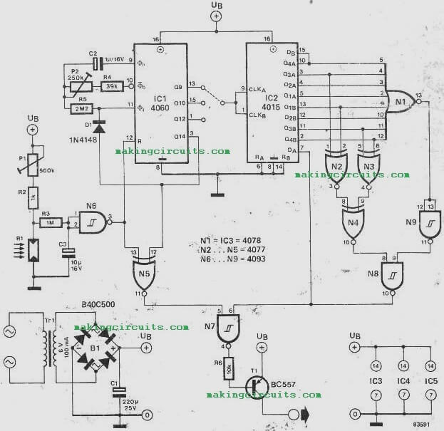

Through the"time that IC1 begins counting, the output of N5 shall be logic '1' although the output of N7, and for that reason transistor T1, will continue to be unaltered right up until a logic '1' additionally shows up from N8. That will naturally be produced by lC2 and its affiliated gates. In the period that IC1 is counting it really is feeding time clock pulses to lC2.
These are extracted from the Q9, Q10 or Q12 outputs from pin13, 15 or 1) of IC1. The Outputs of lC2 along with gates N1 . . . N4, N8 and N9 form a quasi random generator that, by way of gate N7, regulates transistor T1 and clicks the house lights off and on.
This with any luck , puts off our thief buddy by offering the look and feel that the residence may possibly not be as vacant as he might have appreciated! Following a certain time period (1 to 3, 5 hours), output 14 of IC1 ultimately comes back to logic '1'. This leads to numerous things transpire. Through diode D1 it prevents the internal clock oscillator.
This subsequently retains Q14 at logic '1'. At this point gate N7 is prohibited hence switching off the house lighting. Just about all will stay at calmness with the house (our phantom residents tend to be in bed) until the subsequent night when the course of action commences once again. By now our frustrated robber has long gone off to fewer active homes!
Adjustments of the random generator is reasonably easy. The sensitivity of R1, that is the light degree where N6 chooses to change, is defined by P1.
The entire functioning time (of IC1) is scheduled by P2 while the random ‘pattern’ depends upon which of the Q outputs of IC1 is employed to clock IC2. When the random generator is not needed in that case naturally lC2 and its assortment of gates could be overlooked. Nevertheless, remember to plug pin 6 of N7 to the positive supply rail. The house lamps could be started up and off using a relay linked to T1.
Be careful that the maximum current consumed by the relay doesn't go over 50 mA. In case more current becomes necessary at this stage, T1 and the mains transformer should be upgraded.
One last notice. The LDR for this anti burglar house light circuit must not be installed in a condition where road lamps or car headlamps might trigger fake activation of the circuit.
In case this would transpire the house lamps could possibly go on and Off through the night. Our insistent thief could possibly arrive at the realization that there is an all night celebration happening and choose to drop in in the end