


Here we learn how to create an anti corrosive probe circuit for water level sensors, which will ensure that the water has minimum impact on the probes and does not cause corrosion in the long run.
A number of level sensors which work with metal terminals use DC power, that, eventually, corrode as a result of the effects of electrolysis triggered by the water and DC current between the sensing leads.
In order to avoid this particular impact, we could use an oscillator with which the existence or lack of the water will be recognized. With the lasting change of the direction of the current (since it is ALTERNATING CURRENT current), electrolysis would not happen and therefore, the terminals be preserved longer during exposure to said water.
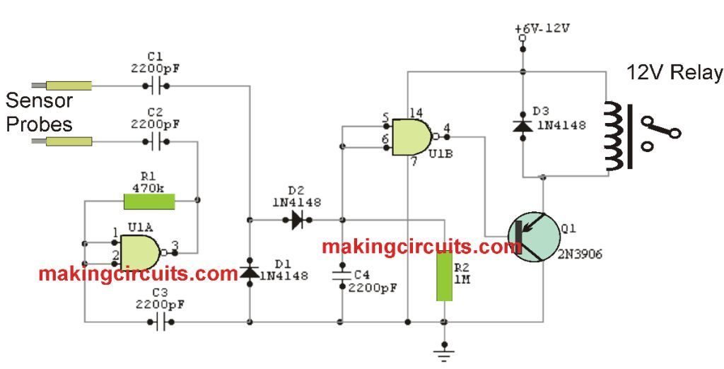
The test probes are supplied through a couple of capacitors whereby only the AC current created by the oscillator designed with gate IC1A flows.
Each time a water meets the two ends of the tester an alteration in the current takes place, which after being rectified by diodes D1 and D2 gets to the inputs of gate IC1B. This gate amplifies mentioned current and regulates the transistor Q1 that subsequently energizes the relay based on the status of the sensor's probe points.
With the relay you are able to switch ON/OFF a pump, an alarm, a lamp, a motor and in brief, just about any electrical system which executes the control activity that the sensor has been intended.
Circuit Diagram
