


The submit reveals an aquarium feeder timer circuit which maintains a couple of nonstop procedures according to a fixed timing sequence by means of the particular pot controls.
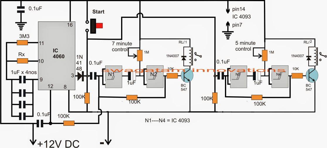
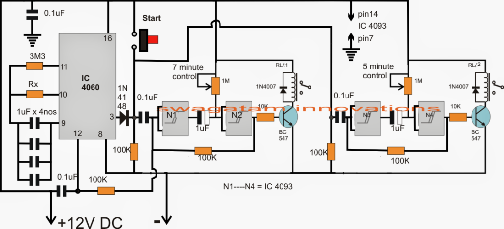
As demonstrated in the suggested fish feeder timer controller circuit, N1, N2 and N3, N4 are the four NAND gates from the IC 4093, set up as flip flop timer phases.
N1, N2 forms the 7 second delay timer, the period might be modified and set with the aid of the 1M pot, exactly the same N3, N4 is wired up as the second 5.2 second delay generator stage.
IC 4060 is intended as the 24 hour timer circuit for the needed cycling of the preferred time sequences.
When the circuit is operated, the 0.1uF capacitors at the inputs of N1 and N3 ground the specific inputs via the 100k resistors, providing an adverse latch across gate outputs, which often maintain transistor relay driver turned OFF.
Right now, for beginning the circuit the "start" button is pressed which reverts the gate latches to positive turning on the relays at the same time. This problem forces pin12 of IC 4060 to turn out to be high to ensure that it remains disabled for the present time.
According to the presented settings of the 1M pots, after nearly 5 minutes the capacitor at the N3 output charges up first forcing the N4 input to go high which one more time returns the latch to negative switching off the 5 second relay first, precisely similarly N2 relay follows and gets shut OFF after next 2 seconds.
The above scenario leads to the output of N2 and the input of N1 to go "low" which means that now pin12 of IC 4060 is allowed at the needed "low" which enables it to commence its counting until the mentioned 24 hour time is elapsed, when its pin3 goes high leading to an automatic activating of the above described cycle.
The method right now maintains repeating forever provided that the aquarium feeder circuit is held in the powered condition.
