

ON SEVERAL events it is really beneficial to manage to establish the frequency of an audio signal. Usually, the consistency and cost of a commercial frequency meter is not really justified.
This little frequency meter circuit , employing just a few components will give you a signal of frequencies through 50Hz to 10kHz having an accuracy mainly based on the calibration of the instrument.
The audio signal of which the frequency is to be established is fed into the input terminals of the unit and the calibrated dial adjusted till a 'null' is acquired whilst hearing the signal by way of a pair of headphones, or maybe a single crystal earpiece.


We claim that the components be mounted in one of the small aluminum miniboxes which one can find conveniently at low priced. Our prototype unit had a 4" x 23/4" front panel, however a larger box will certainly permit a larger frequency scale to use thus delivering much better resolution.
In addition to this a larger box enables input terminals and output socket to be mounted on the front panel along with the frequency null controls. Remember that the dual potentiometer is a logarithmic type and is wired in a way that the frequency scale raises with anti clockwise rotation.
This leads to a more linear scale (less cramped at the high end) than if wired conventionally. Any specific earpiece or headphone are useful to locate the null but ideal performance will probably be acquired with all those possessing an impedance of around one thousand ohms.
The easiest method to calibrate your meter is to compare it with a good quality oscillator and mark your scale to suit. Keep in mind that the majority of potentiometers have a manufacturing tolerance of ±20% and therefore our front panel drawing might not be proper for your potentiometer.
If an oscillator is not accessible however you do have an ohm meter then calibration could be completed by measuring the settings of RV2 (turned off from the circuit) and marking the scale as demonstrated in Table 1.


To make use of the this frequency meter circuit, couple the audio signal into the input terminals and adjust RV2 to a point in which the signal drops off. Adjust RV1 to increase the null and .13V2 again for the final setting.
The frequency of the incoming signal will then be read from the front scale. Exactly what could possibly be easier?
How it Works
The frequency meter circuit is the one about a Wien bridge which often when employed for frequency measurement provides the form displayed below:-
If Cx = Cs Rx = Rs, and Rb = 2π
then f = 1 / 2πCs Rs
or Rx = Rs= 0.628 f
where c. = C, = 0.1µf. Our calibration chart was worked out using this last formula. At the frequency in which the reactance of C, equals 12, and also C. = R., the series network comes with an impedance of 1.414R and phase angle of 45%.

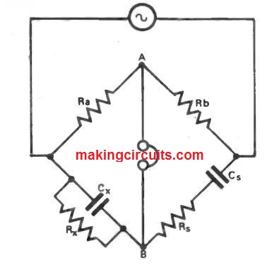
The parallel network possess an impedance of 0.707R and also the same phase angle. The signal at point B will as a result be in phase with the input level, but attenuated to 1/3 of that level.
If Rb = 2Ra the signal at A may also be attenuated to 1/3 of the input. Therefore the bridge is balanced and the signals at A and B is going to be equal in amplitude and phase and a null will happen at that frequency.
At any other setting of the potentiometer the phase angle and amplitudes will probably be in a way that an increased output is acquired.
The particular sections of the dual gang potentiometer in no way track one another completely so because of this RV1 continues to be incorporated to acquire finest null at any point on the scale.