In the earlier post we mentioned the charger controller, the battery high/Low controller and the light sensor sections of the suggested 40 watt automatic solar street light system circuit. This page will highlight the providing steps involved in the PWM managed LED module circuit.
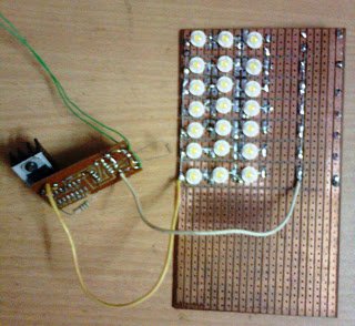
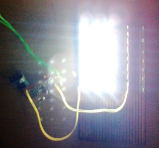
The circuit demonstrated below shows the LED lamp module comprise of 39 nos. 1 watt/350 mA high bright power LEDs.
The entire array is created by hooking up 13 number of sequence connections in parallel, containing 3 LEDs in each series.
The above set up of LEDs is fairly regular in its configuration and would not concentrate much significance.
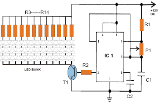
The real essential part of this circuit is the IC 555 section, which can be set up in its typical astable multivibrator mode.
Within this method the output pin#3 of the IC produces certain PWM wave-forms which is often modified by setting the duty cycle of the IC properly.
The duty cycle of this configuration is modified by setting P1 according to ones choice.
Considering that the setting of P1 also chooses the illumination level of the LEDs, ought to be completed with care to generate the most worthwhile outcomes from the LEDs. P1 also turns into the dimming control of the LED module.
The inclusion of the PWM design here performs the key role as it significantly decreases the power consumption of the associated LEDs.
If the LED module could well be hooked up straight to the battery without the IC 555 stage, the LEDs could have utilized the full stipulated 36 watts.
With the PWM driver in operation, the LED module now utilizes about 1/3rd power only, that is around 12 watts yet pulls the highest stipulated illumination from the LEDs.
Such things happen simply because, as a result of the provided PWM pulses the transistor T1 continues to be ON only for 1/3rd of the standard time period, switching the LEDs for the same shorter period of time, in spite of this on account of determination of ideas, we come across the LEDs to be ON constantly.
The high frequency of the astable tends to make the illumination very sturdy and no vibration might be identified at the same time our vision is in motion.
This module is built-in with the earlier talked about solar controller board.
The good and the harmful of the presented circuit ought to be merely hooked up to the appropriate points over the solar controller board.
This concludes the complete justification of the suggested 40 watt automatic solar LED street lamp circuit project.

For those who have any queries, you might show them by means of your feedback.
Constructed prototype readily available for INR 5000/- All Inclusive, with all part numbers unchanged.
Parts List
R1 = 100K
P1 = 100K pot
C1 = 680pF
C2 = 0.01uF
R2 = 100 Ohms
T1 = TIP122
R3----R14 = 10 Ohms, 2watt
LEDs = 1 watt, 350 mA, cool white
IC1 = IC555
In the final prototype the LEDs were installed on unique aluminum based heatsink type PCB, it is highly suggested, without which the LED life would weaken.