


The following circuit is a temperature or climate regulated programmed fan speed regulator circuit.Let's find out more about the presented design.
As can be viewed in the presented diagram, a relatively easy idea continues to be executed in the presented design of a climate controlled or temperature controlled fan regulator circuit.
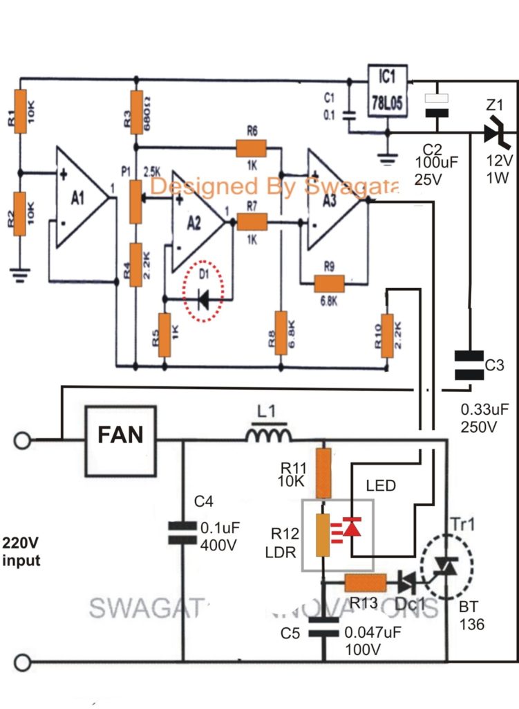
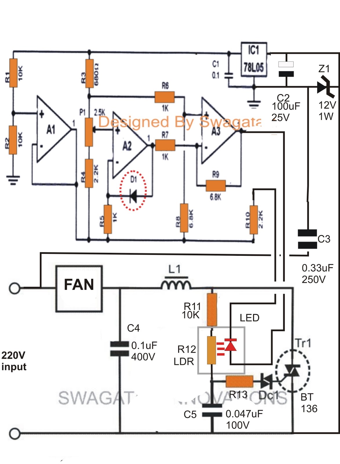
A1, A2, and A3 are the 3 opamps from the IC LM324 which can be set up as voltage comparators and amplifier.
The diode D1 which happens to be a standard "garden diode" has a very fascinating "drawback", it changes its forward voltage drop by 2mV as a reaction to every degree rise in the ambient temperature or the temperature surrounding it.
The above disadvantage of the device turns into our advantage here, simply because the feature here is exploited for sensing the ambient temperature of the premise.
The various voltage across D1, as a reaction to the varying surrounding temperature is efficiently amplified at the output of A3.
The above amplified reaction is given over an LED/LDR opto coupler, where the LED turns into the output load of A3.
For that reason the illumination of the LED differs consequently as a reaction to the temperature variations, it could be brighter with raising temperature and vice versa.
The above illumination drops over the built in LDR of the opto, which often differs its strength in accordance with the above details from D1.
Considering that the LDR is set as the gate control resistor of the dimmer circuit comprise of R11, C5, R13, DC1 and the TR1, the voltage across TR1 begins regulating the mains AC in keeping with the fed LED/LDR reply.
When the LED is bright (at higher temperatures), the LDR resistance lowers. enabling the triac to deliver much more current. This enhances the speed of the fan, and when the LED/LDR reply diminishes (at lower temperatures), the speed of the fan also reduces.
A compact power supply comprise of C3, C2, Z1 provides the essential filtered DC to the IC LM324 temperature sensor configuration for the meant procedures.
Idealy P1 ought to be modified such that the LED just simply commences glowing at about 24 degree Celsius, starting the revolving of the fan at the minimum level.
D1 ought to be held exposed well outside the enclosure so that it is going to feel the fan breeze instantly.

Caution - THE CIRCUIT IS NOT Identified FROM MAINS AC...... Be Particularly Very much CAUTIONED WHILE Constructing AND TESTING THIS CIRCUIT.