


The post explains a simple dark triggered porch light or corridor light circuit using a single IC 741 and few other passive components.
This arrangement enables you to automatically switch on your porch lights while when evening stes in or at nightfall.
It could additionally be applied to activate the backyard lights at night and switch them off in the morning at daybreak.
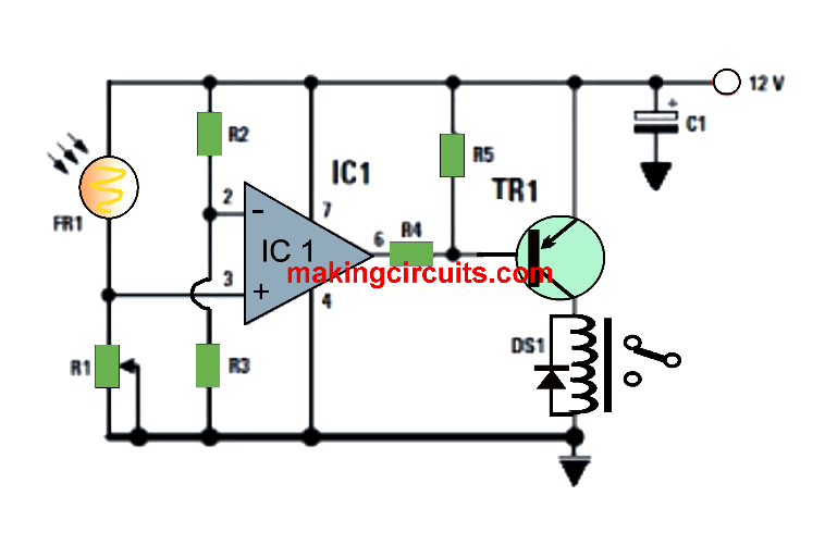
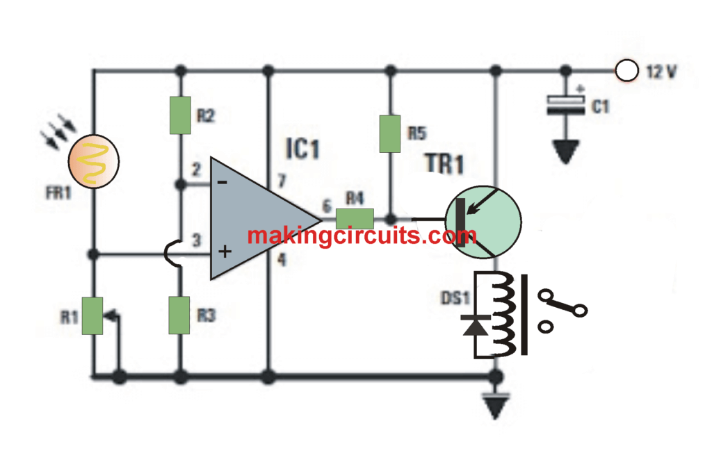
For a photosensitive component, we employed a photoresist (LDR), referenced FR1 in the plan.

The pin 3 (non-inverting) of the opamp IC1 is coupled to the junction of the LDR and the trimmer R1. The LDR is coupled to the + 12 volts and the trimmer to ground, the installation makes up a bridge connected with adjustable values.
The opposite (inverting) pin of the same opamp is attached to the junction of the two resistors R2 and R3, R2 being linked with +12 volts and R3 to ground, the construction comprises a bridge of set value. The tenson at the center is 6 volts.
For as long as the LDR is lit up by a light source on the pin 3 of IC1, we possess a positive voltage bigger than that existing on the pin 2 and therefore the output pin 6 of IC1 reaches logic level 1 + 12 volts).
The resistor R4 consequently find it difficult to polarize the transistor that is a PNP, the relay as a result continues to be inactive.
Once the LDR is positioned in the dark, on the pin 3 of IC1, we get a positive voltage below that's existing on the pin 2. Because of this, the output pin 6 of IC1 reaches logic level 0 the ground).
The resistor R4 is as a result grounded and the base of the transistor TR1 is biased (PNP). The last mentioned then gets conductive and the relay put into its collector is turned on, making it feasible to toggle any load.
The trimmer R1 attached in line with the photoresistor acts to determine the sensitivity of the detection.
Parts List for the above explained automatic darkness activated porch light circuit
R1 = 10 kΩ preset
R2 = 10 kΩ
R3 = 10 kΩ
R4 =1.2 kΩ
R5 = 1.2 kΩ
FR1 = Photoresist
C1 = 100 μF electr olytic
DS1 = Diode 1N4007
TR1 = PNP BC557
IC1 = μA741
Relay = 12 V 400 ohms
Porch Light Controller Circuit
This porch light controller circuit controls the brightness of a light bulb, such that its brightness is somewhere around inversely relative to the ambient lighting conditions.

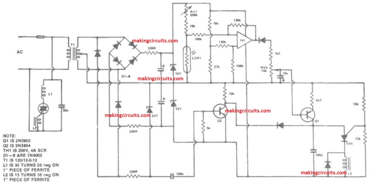
This can be helpful for a porch light, which may start to turn on at dusk, reaching full brightness late in the evening.
During day time it could turn off once again. The dimmer includes TH1 and their connected components. Q2 supplies synchronisation pulses.
RV1 efficiently alters the time of day at which the light switches as well as RV2 alters the highest level brightness of the bulb.
The LDR is attached to a differential amplifier whose output voltage increases once the resistance of the LDR is over around 600 kilohms (corresponding to dusk) and gets to a optimum once the resistance is all about six megohms (corresponding to total darkness).