

This automatic garden watering circuit will sense the moisture level of the garden or pot soil and switch ON a connected water supply system to restore the moisture level of the soil so that the plaits remain healthy and lively.
A specifically eye-catching application requires the kind of automatic watering of valuable indoor plants. The circuits tend to be pretty much easy, even though deliver significant curiosity about their preparation, construction and use.
WORKING PRINCIPLE
Soil conductivity may differ along with moisture content, in order that a complete or a relative measurement of conductivity could be converted right into a corresponding measurement of moisture content.
Detailed instrumentation continues to be employed for years in places like agricultural research stations to produce extremely precise determination of soil moisture content and also to manage plant environments.
On the other hand, intelligent LISP of a quite simple arrangement delivering simply reasonable indications can be extremely beneficial.
One arrangement to be referred to produced a tone, the frequency of which would depend on soil conductivity, that is certainly, on moisture content.
One more arrangement activates an external feature once the soil conductivity drops beneath a fixed level.
The reader can easily obtain important knowledge to accomplish use of these types of arrangements by researching their own soil conditions.
SOIL CONDUCTIVITY
If an ohmmeter is linked to two wires pushed a few centimetres into the ground, a resistance reading will probably be attained. This resistance differs while using dampness of the soil.
Nevertheless, it is really an over simplification, as will probably be identified in the event the ohmmeter connections are reversed almost undoubtedly an alternative reading will likely be acquired.
The problem turns into much more exciting in case a high impedance voltmeter on a low range is attached to the wires, as a reading will most likely be received.
This potential might come up in several techniques or in a combination of means. Stray currents will often be located, especially around dwellings, arising from ground returns of power reticulation systems, galvanic action at buried waterpipes, and many others.
Additionally, considering that the soil most probably won't have a neutral pH balance, but actually will be either acidic or alkaline, two electrodes will themselves develop a battery action. Along with all this, soil qualities differ considerably.
In the author's situation, resistance (reciprocal of conductivity) readings which formed section of a preliminary exercise to get the "feel" of things varied substantially in unsurprisingly similar soils measured simultaneously.
For instance, relatively thin wires, around 18 gauge tinned copper, showed readings varying among 15 k and 200 k for what seemed to be a fair range of dampness in good, "imported" garden soil.
The use of thin wires was discovered less dependable and constant compared to use of flat electrodes or substantial rods. Flat electrodes along with efficient surface areas of, say, 3-4 square centimetres in similar circumstances developed a range of 10 k to 25 k.
In an open yard with a heavy clay sub -soil and little dirt on top, two 8 gauge rods around 25 mm apart provided readings of 800-2000 ohms the day after a good rainstorm, and up to 15 k (on average) after having a couple of dry days.
Indoor plants certainly are a unique case since they possess merely a limited amount of water accessible, that is, the soil being limited to a pot, are not able to call up sub surface moisture as takes place in the open garden.
Potting soils can easily dry out to generate extremely high resistance values, say several hundred thousand ohms even though considerable electrodes are employed.
Not surprisingly this particular signifies a common condition when a plant will certainly by now get completely wilted.
THE PROBE
The probe for this automatic garden watering circuit usually takes many different forms, being generally two spaced electrodes placed within the soil. Nevertheless, probably the most effective type consists of at least two flat electrodes, instead of wires, despite the fact that wires tend to be suitable above 12 gauge and joining into rods.
In any event a fairly considerable exposed surface area of, say, 3-4 square centimetres generates suitable operation generally in most soils. For long lasting insertion as well as for use with soft, friable soils, flat electrodes will be found most eye-catching, whilst for portable use with heavier soils, rod electrodes are usually most effective.
Although the facts are optional and dependent constructor's workshop resources, The electrodes needs to be created from material which could not really corrode.
Monel metal or stainless steel are best suited. Temporary experiments with tin plate are okay, but something better is required for long lasting use.
THE WATER TRIGGER
The second device is demonstrated in Fig.2. Its feature is mainly the constant supervising of soil moisture content responding to a fall below a predetermined level to set off an action.

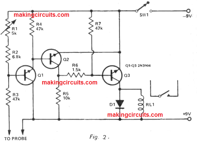
This circuit includes an effective trigger, which usually functions the relay RL for values of soil conductivity below a level preset through the 5 k variable resistor.
The soil conductivity is noticed by a probe attached to the terminals displayed, the circuit really is easy and efficient, and may work ranging from 6 and 12 volts or even more, provided the supply voltage delivers adequate energisation for the relay.
If a very low current relay is employed, a suitable restricting resistor could be placed in the common emitter leads of Q2, Q3. The only point actually is need of focus in this circuit is the base circuit of Q1, right here comprising the probe terminals, two fixed resistors (47k and 6.8k) and a 5k variable resistor.
Presently there are two possible techniques. One can possibly place a large value of variable resistor (say 250k - 500k) instead of the 6.8k fixed and 5k variable revealed.
This constitutes a circuit that may acknowledge numerous values throughout the probe terminals, but actually will result in the adjustment of the variable resistor being far too wide, and all cramped at one end.
The choice is to consider the most likely range of values throughout the probe terminals, depending on tests of the kind explained previously, after which select values to suit.
To find out exactly how this really is carried out, the author's case is going to be proved helpful through. The triggering point of the circuit is by using around 1.25 volts at Q1 base, but do not attempt to measure it with a low impedance voltmeter.
This voltage corresponds to a supply voltage division at Q1 base of 1.25:7.75, in order that the voltage between Q1 base and the positive supply rail is 6.2 (7.5 - 1.25) times the voltage amongst Q1 base and the negative rail.
As a result the resistances in the two parts of the circuit must have exactly the same connection. This neglects 01 base current, which includes fallen to a negligible value close to the triggering point.
At first a range of 500-25,000 ohms across the probe terminals was selected as being proper for the application meant, depending on test plus a margin. For the 500 ohm case, as a result, 47k + 50 = 6.2x, where x is the resistance Q1 base to supply negative.
This generates x = 7661 ohms. Likewise for the 25k case, 47k + 25k = 6.2x, so that x = 11613 ohms, this indicates a variation in x of 11613 - 7661 = 3952 ohms. Even so, it is really an clumsy value, the closest reasonable value being 5k.
Then 11613 - 5k = 6613, the most obvious option for the fixed resistor being 6.8k. Checking back then using these values, for 5k + 6.8k = 11.8k, so that + 47k = 73.16k (11.8 x 6.2), so that the probe resistance is 73.16k - 47k = 26.16k. For 6.8k alone and the 5k variable all out of circuit, the probe + 47k = 42.16k (6.8 x 6.2), providing a negative value for the probe resistance (42.16 - 47 = 4.84).
Therefore the preferred values contribute towards a probe variation of zero to 26.16k ohms, somewhat wider compared to needed. Similar easy calculations will give values ideal for any other range of probe values.
WATER TRIGGER APPLICATIONS
Among the circuits of Fig. 1, except the probe connections, could be linked into the circuit of Fig. 2 instead of the relay and protective diode. A resistor of around 1k might also generally be required in the common emitter lead of Q2, Q3 and Fig. 2.
This combination attracts around 8-10 mA in the alarm situation. Although the most significant application of the trigger circuit is as an automatic waterer.
Think about the case of an indoor planter box. The probe will certainly reveal water content in the soil and trigger the circuit at a preset point. The relay is utilized to work at low voltage water pump, for instance an aquarium pump, to pump water from an obtainable supply into the plant container.
If the water is well allocated over the surface, to illustrate employing a meandering tube quite a few small holes, the soil moisture content will probably be increased pretty uniformly till the probe determines the minimum level continues to be left behind. At this point the circuit resets and awaits further transpiration and evaporation.
THE MOISTURE ALARM
For adding a moisture alarm or buzzer to the automatic garden watering circuit we can employ the following designs using junk box parts and two recycled 2N270 Ge pnp transistors is viewed through Fig.1

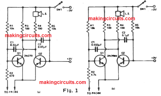
Here, a low impedance ear plug could possibly be utilized in lieu of the speaker. While using probes in air, the circuit provides a consistent low pitched tone, which in turn raises in pitch as the probe is placed in the soil.
The higher the pitch the higher the moisture content. In cases of very high soil conductivity the note may possibly go above the level of hearing; in this instance raise the 0.22 mfd capacitor till the highest audible pitch is received using a saturated area of soil.