


In this exhaustive article you will learn all the basics of electrical technology, which will include definitions of various electrical parameters, descriptions of electrical concepts, and evaluations of formulas and electrical equations.
Drift Velocity, Drift Current and Electron Mobility
The definition of drift velocity may be fully understood by visualizing the haphazard motions of free electrons in a conductor. The free electrons move around in a conductor with randomly accelerating velocities and haphazard directions.
If we put on an electric field over the conductor, the arbitrarily switching electrons encounter an electrical field in the direction of the field.
Because of this field, the electrons tend not to lose their random movement, but they move in the direction of greater potential by their random motion.
Meaning the electrons wander in the direction of higher potential with their randomly changing motions.
Therefore, each and every electron get a net acceleration towards greater potential end of the conductor, and we relate this net velocity as the drift velocity of electrons. I hope you all have now understood the meaning of drift velocity.
The current because of this drift movement of electrons within an electrically pressured conductor, is called drift current. It is as you can imagine that every electric current is actually "drift current".
Drift Velocity and Mobility
You will find a few free electrons always within any metal in room temperature. More technically, at any temperature over a absolute zero, there has to be a minimum of a few free electrons in case the material is conductive, for instance metal.
These free electrons within the conductor relocate aimlessly and quite often clash with heavier atoms and bounce of their path of motion all the time.
Whenever a constant electric field is utilized on the conductor, the electrons start off shifting in the direction of the positive terminal of the utilized potential difference.
However this motion of electrons doesn't come about in a upright manner.
In the course of traveling towards the positive potential, the electrons constantly collide with the atoms and bounce back aimlessly.
Through the collision the electrons drop some of their kinetic energy, but yet again as a result of electric field, they get re-accelerated towards the positive potential and gain back their kinetic energy.
All over again, throughout the further collisions, the electrons partially lose and gain their kinetic energy in much the same manner.
Therefore the applied electric field is not able to prevent the random motion of the electrons inside a conductor.
However due to an electric field, the movements of the electrons continue to be haphazard, but the overall motion of electrons continues to be in the direction of the positive terminals.
To put it differently, the applied electric field causes the electrons to drift in the direction of positive terminal.
Meaning the electrons obtain an average drift velocity. In case electric field strength is increased the electrons are accelerated faster in the direction of positive potential following each collision.
As a result, ultimately the electrons end up gaining a lot more average drift velocity in the direction of positive potential, i.e. towards the applied electric field.
If ν is the drift velocity and E is the connected electric field.
Then,
Where, μe is called electron mobility.
And, the current flow developed by the steadily flowing electrons, because of the drift velocity, is called drift current.
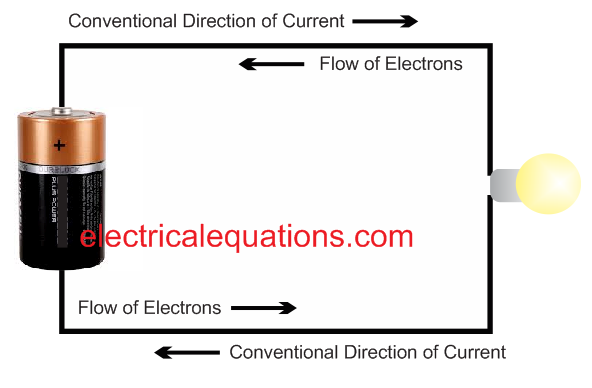
What is Electric Current and Theory of Electricity
Electric current can be defined as the rate of flow of electric charge within two ends of a conductor (metals) with respect to time.
When a voltage or a potential difference is applied across the two ends of a conductor, a flow of electric charge is initiated from the higher potential end towards the lower potential end, with an attempt to balance the charge distribution across the conductor.
This rate of flow of charge with respect to time is called electric currentCurrent Formula If an electric charge "q" coulomb moves across the ends of a conductor within a time span "t", then the value of current could be evaluated as:
1 = q / t
Here "q" is the charge measured in Coulomb, and "t" is time in seconds In a differential form, that is when the charge value may be changing continuously with time, the equation could be written as: i = dq / dt
Unit of Current
As explained above, since current is the ratio of charge transferred across the conductor ends and time taken for the transfer, we can explain one unit of current to be a rate of charge transfer at which one Coulomb of charge is moved from one end of the conductor to the other end. Therefore, unit of current becomes coulomb / second, whose result is measured in Ampere, named after the great physicist Andrew Marie Ampere who researched the above relationship. Ampere is the SI unit of electric current.
Types of Current
Direct Current: It is a type of current which flows through a conductor in one specified direction, without much fluctuations. It is abbreviated as DC.
Therefore direct current can be defined as a current which flows through a conductor in one direction with minimum fluctuations, and with a single polarity.
Alternating Current
Alternating current or AC is a type of current that moves alternately in a forward reverse direction across the conductor ends. It does not have a fixed single direction of movement.
In other words an AC moves within the conductor by changing its polarity and direction of travel many times per second. And this rate of change of polarity and direction of the AC is called its frequency.
This frequency of oscillation for an AC alternates between maximum limit and a lower minimum.
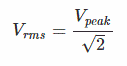
The maximum and minimum limits are called the peak of the AC. The average value of the AC within these peaks is called the RMS value.
Magnetic Effect of Current As we all know that when current flows through a conductor a magnetic field is created around the conductor. This magentic field is created with lines of force oriented with a particular direction depending on the flow of the current. The relationship between between the these lines of force and the direction of the lectric current can be quickly determined through the following "right hand grip rule". Referring to the figure, if we assume the stretched thumb pointing towards the direction of the current, then the direction of the remaining four curled fingers could be assumed to be the direction of the magnetic lines of force
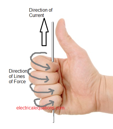
Conversely, suppose if we hold a coiled conductor in our right as shown in the above figure, and pass current through the coil such that the direction of current through the coil is in line with the curled fingers, then the lines of magnetic field developed on the coil would be in the direction of the stretched thumb.
Current in Magnetic Field
When a current carrying conductor is introduced across an external magnetic field, a mechanical force is exerted on the conductor due to the interaction between the conductor's lines of force and the external magnetic lines of force. This mechanical force is directly proportional to the magnitude of current passing through conductor.
Measurement of Current Since this mechanical force is proportional to the magnitude of current applied on the conductor, the concept is effectively used in measuring instruments like pmmc (permanent magnet moving coil instrument), for measuring current passing through a conductor. These instruments are used for indicating current as well as voltage magnitudes in an electrical circuit.
When these are applied for measuring current, the instrument is connected in series with the load, and when these are used for measuring voltage, the connection is usually implemented across the load terminals. When it is used for measuring current, it is referred to as ammeter, and when used for reading voltages, the device is called a voltmeter. When large currents are involved, a "current transformer" is usually incorporated for steeping down the current proportionately, so that an ammeter can be safely used for interpreting the current magnitude and for determining its exact value..
Heating Effect of Current
Whenever current flows through a conductor there is always some degree of loss of energy of the electrons, which is converted into heat. This loss of energy is given as i2Rt joules. Since this is usually dissipated as heat, it is expressed as:
This is referred to as Joule's Law of Heating
Electric Potential
Electric potential at a given point within a field of electricity is defined as the amount of work needed to bring a unit positive electric charge from infinity to that point.
On same principles, the potential difference within a set of two points is defined as the work required for shifting a unit positive charge across these two points
When a body is charged, it gets the ability to attract an oppositely charged body, and repel a body having an identical charge. Meaning, in a charged state a body becomes enabled to do work, and this property of a body to do work in a charged state is called electrical potential of that body.
When a pair of electrically charged bodies are hooked up by a conductor, the electrons begins moving from lower potential body to higher potential body, which implies that current begins streaming from higher potential body to lower potential body depending on the level of potential difference between the bodies as well as the resistance of the connecting conductor.

Therefore, electric potential of a body can be understood as a charged condition of the body that ascertains whether or not the body will acquire or end up giving an electric charge to some other body.
Electric potential is specified as an electrical quantity, or difference of two such quantities, which forces current to move between them. This magnitude is normally calculated from a reference zero level.
The "earthing" or ground potential is regarded as a zero level. An Electric potential over the earth potential is always regarded as positive potential and conversely any electrical potential beneath the earth potential is considered as negative.
The unit of electric potential is volt. When one joule work is done to carry a unit of charge from its existing point to another point, then the potential difference across the two points will be 1 volt. Therefore we can express it with the following equation,
If we assume one point carrying an electric potential of 5 volt, then to be able to get one coulomb charge from infinity to this point, a work of of 5 joule will be required. Conversely if a point possesses a potential of 5 volt and another point possesses 8 volt, in that case 8 – 5 or 3 joules work will be enforced to transfer one coulomb from initial point to the other point.
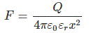
Potential at a Point due to Point Charge
If we assume a point at some distance x from a positive charge + Q, within a space. And If we put a unit positive charge at the mentioned point, then the charge +Q will be subjected to a force, expressed as,
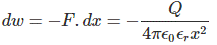
Referring to the image below, if we push this unit positive charge by a small distance dx towards the charge Q.
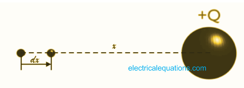
The resultant work done during this movement against the field can be expressed as,
Therefore, to complete the total amount of work in order to transfer the positive unit charge from infinity to distance x, can be expressed by,

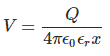
With regards to our previous definition, this is the electric potential of the point developed due to the charge + Q. This may be written as,
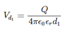
Potential Difference between Two Points
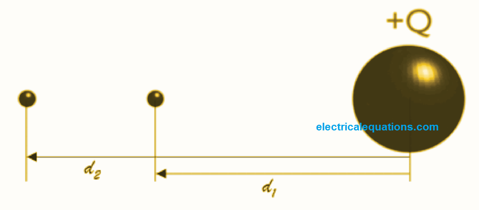
If we consider a pair of points separated by a distance d1 meter and d2 meter from a charge +Q, we can express the electric potential which is d1 meter away from +Q, as,
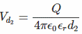
For the electric potential at the point d2 meter away from +Q, we can prove it as,
Hence, we can write the potential difference between these two points as

Voltage or Electric Potential Difference
Before we try to understand the difference between voltage or electric potential difference it'd be important to fist inspect how a charged particle travels through an uniform static electric field.
Voltage Theory
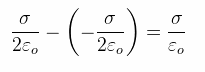
Assume a situation where a pair of parallel plates are plugged across a battery terminals. Let the upper plate be linked with positive terminal of a battery having a positive charged, and the lower plate to negative terminal of the battery having a negative charged. Then these plates will generate a static electric field across them proportionate to surface charge density of the two plates. Considering the surface charge density of the upper plate as σ, the surface charge density of lower plate is going to be - σ. The electric field generated by the solitary positive plate will be equal to the surface charge density divided by 2 times of permeability of the space between the plates. This may be expressed as:

On same principles static electric field produced by the solitary negative plate will be:

Hence the resultant electric field between the plates can be expressed as:
Now imagine a positively charged particle getting into the above expressed electric field. If the particle carries a charge of q Coulomb, then the electrostatic force exerted over that particle will be
Fe = q.E
Where, E is the electric field vector, and is constant for "uniform electric field". Acceleration of the particle can be calculated through the equation,

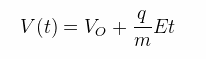
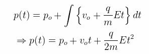
Where, m is the mass of the particle. Therefore velocity of the particle at any given instant t can be calculated from the equation,
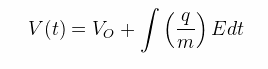
Where, vo is the initial velocity of the particle while it enters the uniform electric field.
Therefore, the position of the particle at any instant "t" is formulated as,
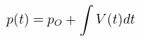
Where, po is the initial position of the particle while it enters into the uniform electric field.
The path will be the function of a parabola. For this reason it may be expected that the motion of a charged particle within a consistent electric field will be a projectile motion with a parabolic path.
Electrical Potential Difference and Definition of Voltage
We could employ an electric field vector to define static electric field in space.
By inspecting the motion of charged particles within an electric field, you can easily anticipate the exact characteristics of this field.
In case the field is quite strong, the moving action of a charged particle within a parabolic course will probably be sharper, when the field is not so strong, the moving course will be milder. However this may not be the most effective method of calculating the strength of an electric field. We may find a different physical quantity which can be easier to evaluate as well as accustomed to define an electric field, and this quantity is referred to as electric potential difference.
Electrical potential V(t) at a given position in the electrical field can be defined as an electric potential energy that is required to bring a charged particle q at that position.
This may be expressed as the charged particle q multiplied by the potential at that position V(t).
Or simply potential energy U(t) = q.V(t).
The SI unit of electrical potential is Volt It is named after the famous Italian physicist Alessandro Volta (1745 - 1827), the inventor of volt. Voltmeter is a device built to measure the potential difference between two points of an electrical circuit. You will find a false impression regarding potential and voltage. Most of us believe that the two are identical terms. But voltage is not specifically potential; it is actually the way of measuring electric potential difference across a given sets of points. Electrical Potential and Electrical Field Vector Both Electrical potential and electrical field vector define the identical factor which is space of electrical field.
Considering that both explain an electric field, the relationship can be expressed as. dV = - E.ds where dV is the potential difference across the two points having a length ds and electrical field vector E.
Potential Difference or Voltage
Using the above voltage theory we can define potential difference as a difference in electric potential energy per unit charge across two given points. Voltage is the work that is required for moving a unit charge across two given points against a static electric field. It is this voltage which is a measure of electric potential difference, and causes electrical current to move within a closed circuit.
What is Electrical Energy: Definition, Formula, Unit of Electrical Energy
What is Electrical Energy?
Before understand electrical energy, if would be useful to first review the definition of potential difference between two points within an electric field.Let's imagine that the potential difference between points A and B in an electric is "v" volts.
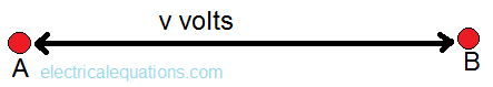
By referring to the definition of potential difference we can explain it as given below:
If a single unit positive electrical charge or a one-coulomb positive charge moves across point A to point B, will result in a work being done with a magnitude of "v" joules.

Alternatively if we imagine in place of one-coulomb charge if q coulomb charge travels from point A to point B, the work done will be equal to "vq" joules.
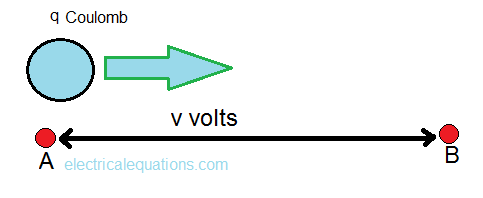
If "q" coulomb charge takes t seconds to travel from point A to point B, then the rate of work done can be expressed as:

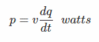
Furthermore, since it is possible to describe work done per second as "power". Therefore, the above term signifies electrical power, which could be written in differential form as:
Here, Watt is the unit of power. Now let's imagine, a conductor positioned in between points A and B, and a magnitude of electric charge "q" coulomb is forced through it. Then the charge passing through a cross-section of the conductor per unit time (second) it can be expressed as:

You may understand that It is nothing but the electric current i, through the conductor.
Consequently, we can write,

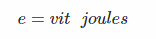
If this current is passed through the conductor for time "t", then the total amount of work done by this charge can be put up as:

This above expression is actually the electrical energy. Therefore, electrical energy could be explained as stated below:
Electrical Energy Definition
Electrical energy is defined as the work done by electric charge.
If some current having a magnitude of i ampere is allowed to pass through a conductor with a potential difference of v volts across it, for a time period of t second, the electric energy developed as a result can be expressed as,
Electrical Energy Formula
The formula for expressing electric power is
Unit of Electrical Energy
Fundamentally we know that the unit of electrical energy is joule. This is equal to one watt multiplied by one second. For commercial evaluations, other units of electrical energy can be also seen, for example watt-hours, kilo watt hours, megawatt hours etc.
Watt Hours
It is simply one watt of power consumed for a time span of 1 hour, wherein the energy consumed is equal to one watt-hour.
Unit, or Board of Trade Unit or Kwh (BOT )
For practical implementations, and also for commercial applications, the unit of electrical energy is expressed as kilowatt hour.
The primary commercial unit which is watt-hour and one kilowatt hour signifies 1000 watt hours.
The utility companies bill the costs of electric energy from the consumer at the rate of kilowatt hour unit. This kilowatt hour is referred to as board of trade unit or BOT unit.
Electric Power
Voltage and current are two fundamental variables of an electrical circuit. However, voltage and current are generally not enough to convey the nature of an electric circuit component. We basically have to find out, just how much electric power a circuit component is designed to work with. We know that a 40 watts electric powered lamp will deliver lower amount of illumination compared to a 60 watts electric lamp. When we shell out money for our electric utility bill, we are in fact paying the charges for electric power consumed for a particular time period. This implies that electric power computation is very important for investigating an electric circuit or system. Power is the rate of energy delivered or used by an electric component with regard to time period.
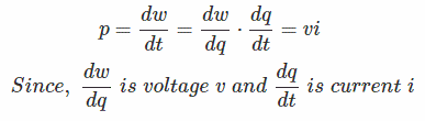
Imagine, a component requires or consumes a power of dw joules for a time of dt second, then power of the component can be expressed as,

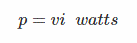
This equation could be also be conveyed as,
Hence, from the above expression we can comprehend that since voltage and current are instantaneous, the power is also instantaneous. The indicated power is dependent on time, and will vary with time.

Therefore, the power of a circuit component is the product of voltage across the component terminals, and current passing through the component. As we have previously learned that a circuit component can either consume or supply power. We indicate the consumption of power by placing positive sign (+) in the manifestation of power. Similarly, we place a negative sign (-) if we symbolize the power supplied by the circuit component.
Passive Sign Convention
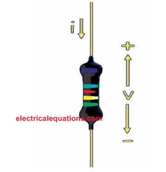
We have a basic connection between the direction of current, voltage polarity and symbol of power of a circuit component. We name this basic relationship as passive sign convention. Whenever current goes in in an component by means of its positive terminal, we place a positive sign (+) prior to the multiplication result of voltage and current. Meaning here the component absorbs or utilizes power from the electrical circuit. Alternatively, once the current via the component departs its positive terminal, we place a negative sign (-) ahead of the multiplication result voltage and current. What this means is the component gives or resources power to the electrical circuit. Suppose a resistor is attached around 2 circuit terminals. Even though, the remaining of the circuit is not displayed in the diagram. The polarity of the voltage drop over the resistor as well as the direction of current via the resistor are indicated in the diagram below. The resistor can be seen as consuming power of vi watts while current i ampere passes through the resistor, via its positive side of the dropped voltage v volt, as shown below:
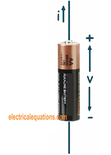
Now we will consider a battery hooked up around two circuit terminals. The voltage polarity drop over the battery and also the direction of current via the battery are indicated in the diagram underneath. The battery can be seen resourcing power of vi watts as current i ampere passes through the battery of v volt via its positive pole as proven.
Electric Charge
Every single matter on this universe consists of atoms. Atoms have electrically neutral property. The reason being, each atom possesses identical quantity of protons and electrons. Protons possess positive charge.
Protons within an atom remain at the core nucleus together with electrically neutral neutrons. The protons tend to be firmly attached in the nucleus.
Thus, protons are impossible to separate from the nucleus through ordinary course of actions. Every electron centers around the nucleus within precise orbits in the atom. Electrons possess negative charge.
The magnitude of electric charge of an electron is precisely the same to that of a proton but are attributed with opposite nature. The electrons are negative and protons are positive.
Therefore, all matter commonly have electrically neutral polarity, mainly because it is created with electrically neutral atoms.
The electrons may also be tightly attached within the atoms however, all may not be. Some of the distant electrons away from the nucleus could be unattached quite easily.
In case a few of these extractible neutral atom electrons of a body are removed, there'll be a shortfall of electrons within the body. Right after elimination of a few of the extractible electrons from the neutral body, the overall amount of protons within the body gets to be greater than total number of electrons in the body. Consequently the body ends up getting charged positively.
Not just a body may hand out electrons, it can possibly take in a little extra electrons, delivered from outside. If so, the body results in being charged negatively.
Therefore, shortfall or overabundance of electrons within a body of matter is referred to as electric charge.
Charge of an electron can be really miniscule and equal to -1.6 x 10⁻¹⁹
This implies, the total 1/16 x 10–19 or 6.28 x 10¹⁹ number of electrons possesses an electric charge of 1 Coulomb.
Hence, if a body losses 6.28 x 10¹⁹ number of surplus amount of electrons, results in being 1 coulomb negative electric charge.
Conversely, if a body possesses 6.28 x 10¹⁹ amount of surplus electrons, the body is going to be with 1 coulomb negative electric charge.
Charged body is an illustration of static electricity. The reason being, the electric charge is restricted within the body alone. Here, the charge is not really moving.
Yet once the electric charge starts moving, it leads to electric current. Electric charge possesses the potential of performing work. Meaning they have potential to both attract an opposite charge or repel exact same characteristics of charge. A charge could be the consequence of breaking up electrons and protons.
Electron Volt or eV
The theory of electron volt is rather simple. We will try to comprehend from the beginning and the fundamentals.
We have already studied that the unit of measurement of power is watt.
that is:
W = VI, where V is the voltage and I is the current.
The current "I" can be understood as the rate of transfer of charge, which means an instantaneous power could be written as:
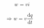
Where, q(t) is the quantity of charge transferred in time t.
We also know that energy is expressed as
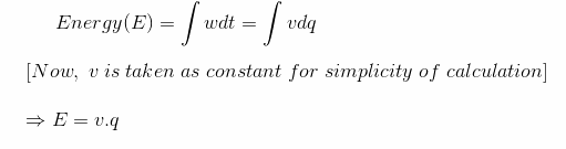
Where, q is the charge in Coulomb across an applied V volts.
From the above energy equation we can understand that the required energy or the amount of work done to move an electric field carrying a voltage "V" by a charge of "Q" coulomb will be QV coulomb - Volt or joules.
So far we have understood that charge on an electron is = - 1.6 × 10⁻¹⁹ coulomb when it has traveled through an electric field having a voltage of 1 volt. As a result the total amount of work required for this will be charge on electron x 1 V

Definition of Electron - volt
One electron - volt is the unit of energy in joules is the amount of work required for bringing one electron against an electric field of 1 volt.
This is a minuscule or micro unit of energy essentially used for calculating at different atomic and electronic levels. Micro unit of energy or electron volt is used for analyzing theories of energy levels in materials, and also a variety of energy categories such as light, thermal, nuclear etc Reference: https://en.wikipedia.org/wiki/Electronvolt
Sinusoidal Wave
To get a better understanding regarding Sinusoidal Wave Signal, we first need to understand what a signal is
What is a Signal?
There are different measurable quantities in the world surrounding us. Some quantities are constant like acceleration due to gravity, speed of light, velocity of sound in air. Some are time-varying like AC voltage, Pressure, Temperature.
It means they change their value as time passes on. Signal simply means the value of any quantity taken over a period of time. Signals are usually time varying in nature. Generally a graph is plotted between values at different time instants. This is called graphical representation of signal.
What is Sine Wave or Sinusoidal Wave Signal?
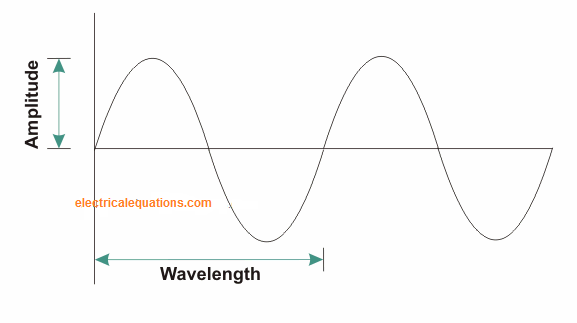
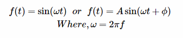
Sine Wave or Sinusoidal Wave Signal is a unique type of signal which can be represented by the function
When Sine wave begins from zero and travels upto positive peak values, goed downwards until zero line zero; and yet again travels to its negative peak values, extends to zero, is considered to have carried out one cycle or single cycle.
The upper portion of sine wave is termed positive cycle and the lower portion is termed negative cycle in a single cycle. For distinct values of time, the Signal provides the values of magnitude at that time. Hence Signal is usually a function of time. Therefore, it is presented as f (t).
The Maximum value of the Sinusoidal Signal is alternatively known as its amplitude (A). Here ω is known as Angular Frequency of Signal and f is the Frequency of Signal. ∅ Is named Phase difference.
Frequency is measured in Hertz (Hz). It indicates number of cycles of signal which occurred within a second. Large ω or large f value signifies that the signal accomplishes more number of oscillations (i.e., moving from positive values to negative values) quicker.
Therefore the Signal is somewhat more Oscillatory with its characteristics. Sinusoidal signal does not have to start off from zero. It could start soon after specific period of time. This can be moment after which Sinusoidal Signal commences is displayed by using phase difference (∅). It is measured in Radians.
Periodic signals are type of signals that repeat their cyclic pattern after specific amount of time. This time frame after which the signal repeats its pattern is known as time period (T) of Periodic Signal. It is inverse of frequency of Signal.
T = 1 / f
Sinusoidal signal is considered as a periodic signal, since its waveform continues repeating, following one Wavelength after another as demonstrated in the Figure above. The mains utility power in our house, offices and industrial sectors are AC sinusoidal signals. The frequency (f) in India and European nations is 50 Hz and in United states it is 60 Hz.
The reason why Sinusoidal Wave Signal crucial?
Sinusoidal signals are crucial both in electrical and electronic engineering fields. Based on Fourier Series Theory, any kind of signal (Periodic Signal) could be expressed only in terms of sine and cosine Signals of several frequencies.
Hence a complex signal could be categorized into basic sine and cosine signals and numerical evaluation results in being straightforward. Therefore it is popularly implemented in electrical and electronic evaluations.
Furthermore, the output voltage in transformers happens to be a time derivative of magnetic flux. Magnetic flux by itself is time derivative of the input voltage. However we would like to have the very same voltage signal both at input and output.
The only characteristics which fulfill this situation are sine and cosine functions. Since sine signal always starts off from zero level or reference, it becomes an ideally preferred system. As a result most of power grid solutions in the present day apply sinusoidal AC voltage. All our domestic products are all specifically designed to work on Sinusoidal AC voltage.
RMS or Root Mean Square Value of AC Signal
The main points that will covered under post are:
- Why rms values are employed in AC systems?
- What does an average and rms value signify?
- The key reason why all AC systems ratings are in rms not in average value?
- The main between rms and average value?
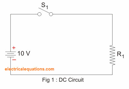
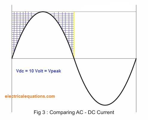
Imagine, a basic DC circuit (figure - 1) and we would like to reproduce it in an AC circuit. We have every part identical, apart from the supply voltage which is at this point is an alternating supply voltage. So , the query is exactly what should be the value of AC supply voltage to ensure that our circuit functions precisely like that of DC.
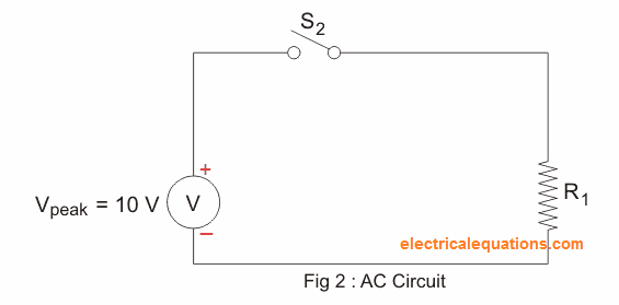
Let us apply an equivalent value of alternating supply voltage (AC Vpeak = 10 volt) like our DC circuit. By executing this we are able to see (figure 3) that for any half cycle the AC voltage signal does not occupy the total area (blue area) of constant DC voltage, meaning our AC signal is unable to supply the equivalent volume of power like our DC supply. Which implies that we have to raise the AC voltage to occupy the identical area and find out if it is delivering the identical level of power or not.
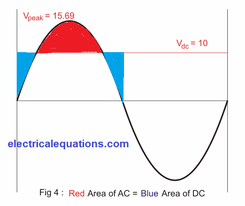
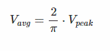
We observed that (figure 4) by raising the peak voltage Vpeak as much as (π/2) times of DC supply voltage we are able to essentially occupy the entire section of DC in AC. In case the AC voltage signal totally symbolizes the DC voltage signal in such a case that value of DC signal is known as the average value of AC signal.
It may appear that AC voltage should deliver the identical level of power as DC, however whenever we switch on the supply, interestingly we observe that AC voltage is delivering greater amount of power compared to DC. This is because an average value of AC resources identical level of charges (joules) but not the identical level of power. Therefore, to obtain identical level of power through our AC supply we have to lower our AC supply voltage.
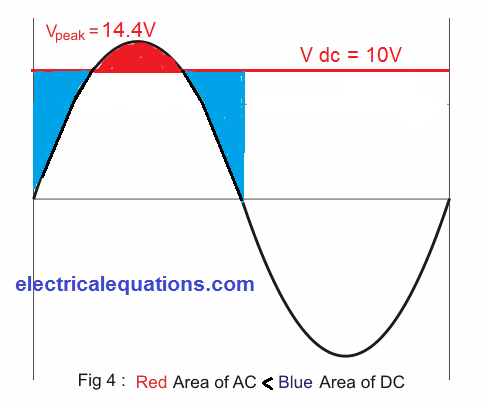
From the above discussion we conclude that: Average value of an AC current symbolizes the equivalent level of charges in DC current.
RMS value of an AC current symbolizes the equivalent amount of power in DC current
AC current requires less quantity of charges to deliver the equivalent level of DC power.
SI System of Units
Units are comprehended to be those tools through which we are able to calculate any physical proportions efficiently. For instance, if we wish to determine length then that may be calculated in meters, centimeters, feet etc, similarly when we need to determine mass then that could be measured in kilograms, grams etc. Therefore to sum up we are able to express several units which may be utilized to determine a specific quantity. Today if we consider other forms of physical quantities we find several forms of units accessible for a specific quantity. This creates the confusion, and one could wonder which one should we pick and what type we must not, for a specific measurement. In case we have several units in hand then there has to be some transformation aspect to convert it into another unit. However that may be quite time consuming, as well as there can be a good probability of error in carrying out the calculations, and if we need to measure that specific unit in the third unit for a given quantity, we might find our self getting the incorrect final results. Thus we find it to be a critical necessity of selecting only standard quantities in measurement. In such circumstance, we pick an individual unit for a specific quantity whose unit is recognized as standard unit. The majority of the measurements are executed with this unit. Therefore the measurement gets to be straightforward but additionally provides value in one single unit for the selected quantity.
SI System of Units
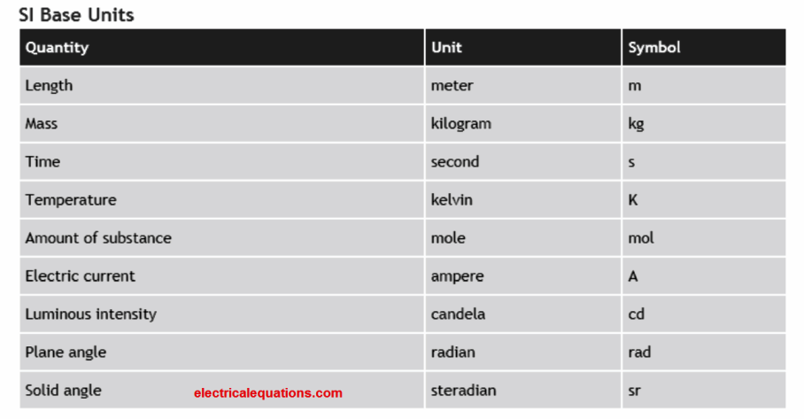
The majority of us understand what SI units are, yet we usually have no idea what the term SI signifies. It basically suggests international systems of units. The units that are used in measuring physical quantities are jointly known as as SI units. It was formulated and recommended by General conference on Weights and measures in 1971 intended for international consumption in the field of scientific, technical, industrial and commercial applications. Today the situation transpires, exactly what units should we decide on? The units that needs to be selected must include the following given attributes It should possess a appropriate size. It must be precisely characterized. It should offer an comfortable access. It should not be dependent on time. It should not alter with the change in physical quantities. The SI units that are manifested without the support of other fundamental quantities like length, temperature etc. The units that can be manifested with the help of the fundamental units are known as derived units. The fundamental quantities and their standard units (SI) are:
Benefits of SI System of Units
- It is a coherent system of units.
- It is a realistic system of units.
- SI is a metric system.
Summary of SI System of Units
Although it offers excellent advantages and today we work with SI units for the majority of the measurements, it is not necessarily totally free of down sides too.
It includes disadvantages like it generally is targeted on just one unit therefore the significance of other units gets thinned down.
Additionally the SI unit is unable to often effectively determine a quantity. For instance, while measuring house area we employ square feet as the unit of area in many of the cases, therefore in such scenarios we might need to change it to the SI units, which is not convenient.
This kind of situation could come up in other predicaments also, however the many positive things associated with SI systems tend to be more prominent, that makes it well-liked and we easily prefer using it in our everyday requirements..
Cyclotron Basic Construction and Working Principle
Before we comprehending the fundamental operating theory of Cyclotron it is important to fully grasp regarding force acting on a moving charged particle within a magnetic field as well as motion of the charged particle within the magnetic field.
Force on a Moving Charged Particle in a Magnetic Field
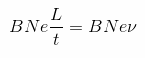
Whenever a conductor of length L meter carrying a current I ampere acts perpendicularly in a magnetic field having flux density B Weber per meter square, then the influence of magnetic force working on the conductor could be given as: F = BIL Newton ---- 1 Now, let us assume we have total N number of free electrons within the conductor across length L meter evoking the current I ampere. ∴ I = Ne / t ---- 2 Where, e is the electric charge of one electron and equal to 0.6 × 10⁻¹⁹ coulomb. So from equation (1) and (2) we get

Here, N number of electrons can be seen as creating current of I ampere. Let's assume these move across a length L meter in time t, consequently drift velocity of the electrons could be v = L / t ----- 4
From equation (3) and (4), we derive the following equation:
This is the force that engages on N number of electrons in the magnetic field. Therefore force on a single electron in that magnetic field can be given as

Motion of Charged Particle in a Magnetic Field
Whenever a charged particle travels within a magnetic field, we may find two extreme situations. The particle travels either along the path of the magnetic field or it goes perpendicular to the magnetic field. If the particle travels along the axis of the direction of magnetic field, magnetic force working on it is given by the equation:
Consequently it will have no force acting on the particle, thus no improvement in the velocity of particle and therefore it travels in a straight line with a fixed velocity. On the other hand if the charged particle travels perpendicular to the magnetic field then it will have no difference in the speed of the particle. The reason being the force working on the particle is perpendicular to the motion of the particle, consequently the force is unable to carry out any work on the particle thus the the particle experiences no change in its speed. Nonetheless this force working on the particle perpendicular to its motion and the direction of the motion of the particle will vary consistently. Because of this the particle can shift in the field in a circular path with a fixed radius and with constant speed. When the radius of the circular motion is R meter we have the following expression:
This indicates that the radius of the motion is dependent on the velocity of the motion. Angular speed and time period are constant.
Basics Principle of Cyclotron
This principle of motion of charged particle within a magnetic field had been applied with success in an equipment named cyclotron. In theory this gadget really is easy but it possesses significant applications in the field of engineering, physics and medicine. The equipment is a charged particle accelerator machine. The motion of the charged particle subjected with perpendicular magnetic field is specifically utilized in the equipment referred to as cyclotron.
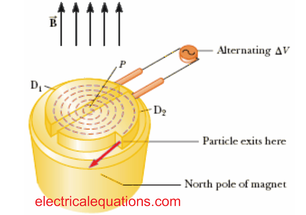
Construction of Cyclotron
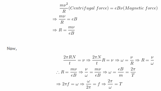
This equipment primarily consists of three crucial structural elements: 1) Large sized electromagnet to create uniform magnetic field in between its two face-to-face placed magnetic opposite poles.
2) Huge electromagnet to generate homogeneous magnetic field between its a pair of face-to-face positioned poles with opposite magnetic orientation.
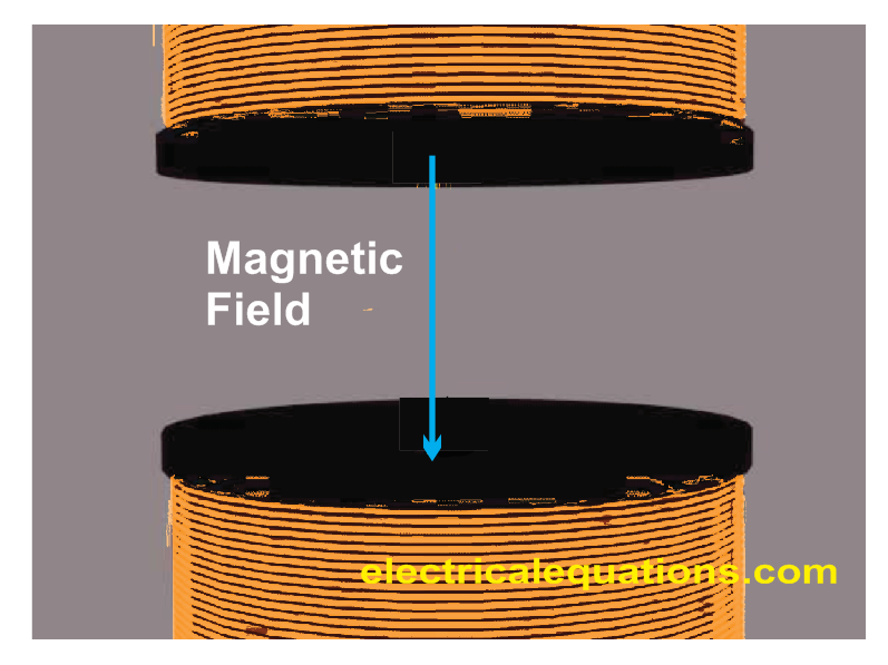
3) A couple of short hollow half cylinders manufactured from high conductive alloys. These elements of cyclotron are classified as Dees.
How it is Constructed
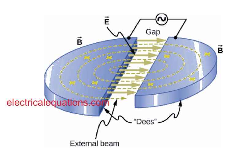
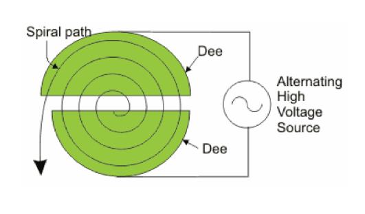
The Dees are positioned face to face between the electromagnetic poles. The dees are positioned in such a way that the effective edges become face-to-face with minimum space between them. Additionally the magnetic flux of the electromagnet cut through these Dees with a precise right angle. At this point both of these Dees are plugged into a couple of terminals of AC mains voltage source such that if one of the Dees gets positive potential then the other shall be in accurate opposite negative potential at that instant. Because the supply is AC the potential of the Dees are switched depending on the frequency of the supply. Now imagine a charged particle is tossed from a position in close proximity to to the center of one of the Dees with some velocity V1. Because the motion of the particle is at right angle to the applied magnetic field, it will have absolutely no change in the velocity, however the charged particle will start following a circular path radially. R1 = mv / qB Where, m gram is the mass and q coulomb is the charge of the subjected particle and B Weber/metre2 is the flux density of externally applied perpendicular magnetic field. Once the charged particle has moved through π radians or 180 degrees it arrives on the edge of the Dee. Now the time period and frequency of the applied voltage source is fine-tuned with the time period of circular motion in such a way that it gives: T = 2m / qB Since the polarity of the Dee on the other side is opposite to that of the charged particle, it creates an attraction from the Dee on one side of the moving particle and a repulsive force from the the Dee where the particle exists, this results in the particle attaining extra kinetic energy.

Where ν1 is the velocity of the particle at previous Dee and ν2 is the velocity of the particle in subsequent Dee. At this point the particle begins moving with this more significant velocity and with a radius R2 metre.
Once again on account of continual perpendicular magnetic field the particle moves an additional half cycle on this new radius R2 meter and reaches on the edge of existing Dee. When this happens , the Dee in front yet again turns into opposite polarity with regards to the other and the particle leaps across the gap in between the Dees by an additional gain in its kinetic qV. This all over again increases the gain in terms of velocity and radius of the circularly moving charged particle. In this manner the charged particle goes into a spiral path of motion with persistently escalating velocity. Which means charged particle keeps attaining to a sufficiently high level of required velocity prior to leaving the cyclotron gun head. If the frequency of voltage source is say f, we can write:
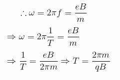
Here, 2π is constant, m, q and B are known, so it becomes possible to evaluate T, and therefore frequency of the voltage source could be written as:qB / 2πm
Application of Cyclotron
Cyclotrons are practically implemented in mainly two ways. One is in laboratories for various physics experiments where extremely highly accelerated photons become crucial, and also for applications involving irradiating of tissues, which also likewise demands and works with highly accelerated photons.
Space Charge
Deposition of charges inside a specific region is called space charge. The space where the charges build-up could be within a free space or a dielectric. Additionally, this collection of charges could be moving in nature or fixed. We will try to comprehend this better through examples.
Examples of Space Charge
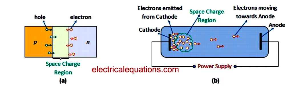
Example 1: Imagine the situation where we bring a p-type semiconductor in contact with an n-type semiconductor. As we all know, n-type semiconductor material includes surplus electrons while this is depleted in the p-type material. Therefore, when both of these are introduced together, the electrons begin switching from n-type to p-type. This results in the electrons and holes existing close to the junction to reunite with one another. Consequently, some area surrounding the junction gets depleted of free charge carriers. This region is simply the space charge region containing immobile or fixed ions (Figure 1a).
space charge
Example 2: Now , let us imagine there's an electron tube connected to a power source. In this scenario, the electrons are going to be expelled from the cathode terminal and these will begin relocating towards the anode.
Having said that these electrons would be unable to get to their destination in a flash i.e. they are going to take some definitive time to accomplish their travelling.
Because of this, these electrons may build up close to the cathode end of the system developing a fog of negative charges. This may lead to the development of negative space charge region (Figure 1b) that may begin travelling under the effect of the applied electric field.
Example 2 shows that the fundamental factor which results in the buildup of charges is actually because the rate of evacuation of electrons is smaller compared to the rate of accumulation.
Meaning , the cathode terminal ejects much more quantity of electrons compared to those that move towards the anode. Also , entangling of charges, drift and diffusion could also be responsible for the development of space charge region.
Additionally if the polarity of the charges comprising the space charge is identical to that of the electrode involved, in that case they may be named homocharges. In contrast, if their polarities are different from one another, then these are known as heterocharges.
Implications of Space Charge
The space charge impact presents a challenge by influencing the conversion efficiency and the output power of thermionic converters.
This is due to the fact that when this kind of electron buildup transpires around the metal surface, it presents an extra obstacle wall for the electrons that are meant to reach their final destination.
This prohibition on the mobility of electrons is encountered by means of repulsion on the released electrons, from the electrons which are existing in the cloud.
The space charge effect that develops in the dielectrics also causes the breakdown of electrical components like capacitors.
This may be due to the applied high voltages, when the electric charges released from the electrode get caught between the gas encircling it.
Exactly the same outcome can also be witnessed leading to the malfunction of power cables that carry high voltages.
Having said that, space charge effect can also be beneficial in a few circumstances. As an example, the existence of space charge region produces a negative EMF on particular tubes which can be helpful of supplying a negative bias to it.
This in turn becomes beneficial since it assists the engineers to enjoy a greater control over the process of amplification, consequently enhancing its efficiency.
Yet one more illustration that may look useful could be that the space charge tends to reduce the shot noise. This is because, basically the space charge influences the free motion of charges through their path. This in turn decreases the quantity of charges that turn up randomly, and thus minimizes their numerical diversification which is actually the shot noise.
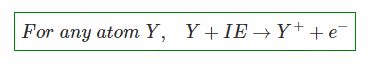
What is Ionization Energy
The capacity of an element to donate its outermost electrons for creating positive ions is revealed by the magnitude of energy supplied to its atoms which may be enough to remove the electrons out of them.
This energy is recognized as Ionization Energy. In other words, the Ionization Energy is the energy provided to an singled out atom or molecule to eliminate its most loosely attached valence shell electron to create a positive ion.
Its unit is electron-volt eV or kJ/mol and is measured in an electric discharge tube where rapidly moving electron collides with a gaseous element to expel one of its electrons. The lower the Ionization Energy (IE), the greater is the ability to create cations.

Ionization Energy
This is often described with the Bohr model of an atom, wherein it takes into account a hydrogen-like atom having an electron revolving around a positively charged nucleus due to coulumbic force of attraction and the electron can just only possess a predetermined or a quantized levels of energy. The energy of a Bohr model electron is quantized and given as below :
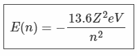
Where, Z is the atomic number and n is the principal quantum number where n is an integer. For a hydrogen atom, Ionization energy is 13.6eV.
The Ionization Energy (eV) can be described as the energy needed to transfer an electron from n = 1 (ground state or most stable state) to infinity. Therefore considering 0 (eV) as the reference at infinity, the Ionization Energy could be expressed as :

The theory of Ionization Energy complies with the facts of Bohr model of atom where it states that electron can revolve around the nucleus within predetermined or individual energy levels or shells manifested by the principal quantum number ‘n’.
As the first electron moves far away from the neighborhood of the positive nucleus, a more significant amount of energy becomes necessary to knock out the next loosely bound electron as the electrostatic force of attraction gets higher, i.e., the second Ionization Energy is higher than the first Ionization Energy
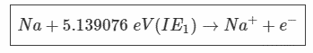
For example, the first ionization energy of Sodium (Na) is given:
And its second Ionization Energy is expressed by the equation:
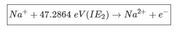
Thus, IE2 > IE1 (eV). This also becomes legitimate in case there are K number of ionization, then IE1 < IE2 < IE3………. < IEk
Metals possess lower Ionization Energy. Low Ionization Energy signifies superior conductivity of the element. For instance, the conductivity of Silver (Ag, atomic number Z = 47) is 6.30 × 10⁷ s/m and its Ionization Energy is 7.575 eV and for Copper (Cu, Z = 29) is 5.76 × 10⁷ s/m and its Ionization
Energy is 7.726 eV.
In conductors the reduced Ionization Energy results in the electrons moving through the entire positively charged lattice, developing an electron cloud.
Factors Influencing Ionization Energy
If we refer to the periodic table, we find the common pattern where the Ionization Energy boosts from left to right and reduces from top to bottom. Therefore the aspects influencing ionization energy could be summarized as follows:
Dimension of the Atom: The Ionization Energy diminishes in accordance with the size of the atom because as the atomic radius gets bigger, the columbic force of attraction between the nucleus and outermost electron minimizes and vice-versa.
Shielding Effect: The existence of inside shell electrons shield weakens the columbic force of attraction between the nucleus and the valence shell electrons.
For this reason ionization energy reduces. More number of inner electrons implies more shielding. Even so, if we consider the metal gold, the Ionisation Energy is higher than silver even though the size of gold is greater than silver.
This is because of to the fragile shielding provided by the inner d and f orbitals for gold.
Nuclear Charge: The greater the nuclear charge, the difficult it may get to ionize the atom on account of greater attraction force between nucleus and electrons.
Electronic Configuration: The better the stability of an electronic configuration of an atom, the higher it gets to pull away an electron leading to greater Ionisation Energy.