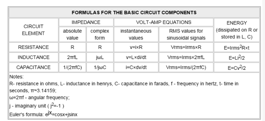
We'll learn a few of the judicious definitions and basic electronic formulas for devices and components. Electronics demands the design and analysis of electronic circuits. In the beginning, this issue was generally known as radio engineering. The expression "circuit" identifies an accumulation of parts whereby electricity current is able to run or that contain electromagnetic fields in their procedure.
Fundamental circuit model and evaluation is situated largely on a couple of Kirchoff's laws, Ohm's law improved for AC circuits, and power relationships (see below). You will find numerous configuration theorems and techniques (for example Thevenin, Norton, Superposition, Y-Delta transform) which happen to be outcomes these particular three principles.
To be able to streamline computations in AC circuits, sinusoidal voltages and currents are frequently characterized as complex-valued functions referred to as phasors. Using phasors we must address algebraic equations rather than differential equations (refer to below). Typically, practical circuit design and evaluation demands an awareness of semiconductor units, integrated circuits, magnetics, DSP, and feedback control.
In this article there exists electricity and magnetism recommendation, basic electronic formulas for devices and components, as well as other critical information.
Fundamental Formula for Transistor and Diode
The attributes of semiconductor devices are analyzed in university lessons. The presentation to the circuits together with functioning of diodes and transistors and fundamental formulas are supplied by assorted books or handbooks. Here are just a few emphasizes.
The I-V attribute of a diode is determined through the Shockley equation:
I=Is×(enVd/Vt-1),
in which Is - the reverse bias saturation current (~10−15 to 10−12 A for Silicon); Vd - forward voltage drop in volts; Vt - the thermal voltage (~0.026V at ambient temperature), n - the "ideality factor" (from 1 to 2). At a restricted current I, voltage drop Vd upgrades by approximately -2 mV/oC.
Inside a bipolar transistor collector current Ic in linear function resembles the base-emitter voltage by the identical Shockley (also known as Ebers-Moll) equation, except for n=1. The collector current works for the base current IB by Ic=IB×h21, in which h21 - static current gain (typically 20-1000). In spite of this, Ic is unable to overrun Vin/|Z|, in which Vin- the supply voltage, Z- net impedance in the external collector circuit. In case Ic extends the earlier mentioned boundary, the transistor is conducts.
MOSFET tendencies may differ using the gate voltage Vg. Whenever Vg <vth, vg="" when="" id≈0.="" current="" drain="" with="" condition="" off="" within="" is="" mosfet="" the="" voltage,="" limit="" gate="" -="" vth="" wherein="">Vth along with the secondary load is such that Vd> Vg-Vth, the MOSFET remains in an active state, wherein Id is proportional to the (Vg-Vth)2 and virtually is unable to count on the Vd. As soon as Id actually gets to particular limit identified by an external circuit, MOSFET get into behaving like a close to constant resistance. During this function Vds≈Id×Rdson, in which Rdson - the ON-state channel's resistance designated in data sheets as a feature mainly of temperature and gate voltage. Power MOSFETs are frequently employed as switching equipment which run in possibly ON or perhaps OFF state.
More will be updated soon under this basic electronic formulas for devices and components article
