In this post we elaborately discuss how to make a passive cross-over filter circuit, a 2-way cross over filter circuit, and a 3-way cross over filter circuit.
Circuit Contributed By: Midlan Bosch

Introduction
Reproduction of a high-quality range of audio frequencies is not achievable by a standard loudspeaker alone. This is where multiple speaker systems come into place whereby every driver is developed to govern one section of the larger audio spectrum. To make this happen, a certain method must be followed so that each driver only gets a band of frequencies for which it was constructed.
The deployment of subwoofers, midrange speakers and tweeter drivers come in handy to manage the distinct frequencies. However, only frequencies lower than the permitted limit must be applied to each driver.
Passive Crossovers
Passive crossover filter circuits provide the required cut-off and roll-off at the set high, mid range and low frequency levels, but since they do not employ active parts like ICs or transistors, the response is not very sharp, and Hi-Fi.
In typical systems, a lone capacitor can be used to restrict low frequencies and permit only highs to a tweeter. Regrettably, this type of capacitor only delivers 6 dB per octave attenuation. With some tweeters, this attenuation is not enough to hold the resonant frequency of the tweeter. Resultantly, the driver could be damaged when worked at high power levels. Furthermore, because other frequencies are present on top of those desired passband causes high levels of intermodulation distortion and overall clogged sound reproduction.
Due to that, every multi-way system deploys networks which deliver at least 12 dB per octave attenuation, in the stopband, to manage the audio band presented to each drive unit. A normal network for a 3-way system is shown in Figure 1.

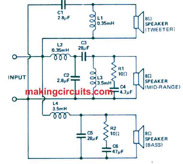
It is important to keep the coils fixed to DC resistances which are smaller than 1 Ω to ensure power losses very low in such networks. Moreover, we would also need to include the high value of capacitance which equips non-polarized electrolytic terminals. One of the disadvantages is the tolerance is positive or negative 50% on these non-polarized electrolytic terminals!
This means that a cross-over utilising them could effortlessly provide a system which had peaks and/or profound holes in the retort. Such capacitors own disadvantages such as limited life, relatively low operating voltages and issues due to leakage. Therefore, all decent crossovers deploy the application of polyester capacitors but unfortunately, they are costly.
In simpler words, for a multi-way high-fidelity system, the cross-over is expensive, and in some cases, they can cost as much as the bass driver. Many try to overcome this problem by modifying by employing lighter wires and electrolytic terminals, but they then wonder why the sound is not as good. It is fundamental to remember that getting a decent crossover is most important, even if you had to compromise on the woofer.
How it works
In the beginning, the input signal is boosted by IC1/1. Switch S1, as well as R3 and C2, deliver a maximum of 10 dB of amplification below 50 Hz at a rate of 6 dB per octave. The frequency at which the amplification arrives may be modified by choosing a value of C2 such that its reactance is 220k at the frequency. At this point, the woofer’s value will be typically 3 dB down. Therefore, if the turnover frequency is desired to be 100 Hz, you must halve C2’s capacitance.
If the boost feature is not needed, R3, C2 and SW1 must be removed and a link connected between points B and C. The mid-frequency gain is configured by R2/R1 to around 13 dB and the input impedance is identical to R1’s value, which is 47 kΩ.
Active Crossover Circuit
Active crossover filter circuits employ an active electronic part such IC or transistors for implementing the various cut-off thresholds for the low, high and mid range frequencies allowing only the matching ranges of distinct frequency bands and Hi-Fi music output for the woofers, mid range and the tweeters.
Since we now understand an efficient cross over could be costly, we could look into other options that would use the additional money more practically. The approach in the discussion is to use an electronic crossover, after the preamplifier, trailed by individual power amplifiers for each driver. This is sustainable because a power amplifier can be constructed with the same budget you would need for a passive crossover. This method works well because some well-developed crossovers have grave issues. On top of being expensive, they waste power, bring down the damping factor (within the cross over region damping factor can fall to less than unity) and they can only operate properly into their described load impedance. Practical drivers display their normal impedance surpassing a tiny amount of their passband, and impedance might substantially rise to multiple times the normal value at the high end of the range. We can compensate for this to some degree by employing additional networks across the driver (the series RC networks as shown in Figure 1. However, it is tough to modify the cross-over frequency and also quite challenging to slash the cross for best outcomes.
Still, if we wish to use an electronic crossover having active filters, we alleviate many issues mentioned in a single hit. The big and expensive inductors and the bulky and costly capacitors are removed. Damping factor is reinstated (because of the individual amplifiers utilised to power each speaker directly) and it becomes fairly simple to alter or snip the crossover frequency as needed.
Moreover, as electronic cross overs may possess gain, we can easily match the various drivers of the system for sensitivity. This can be only made possible in passive designs by weakening the extra sensitive units down to a level of the smallest sensitivity. Regrettably, this method could waste the amplifier’s power.
There are some drawbacks even with active cross-over circuits. We normally utilise operational amplifiers to implement the filters in active components. Due to that, the bandwidth and noise become considerations. Moreover, as mentioned before, an individual amplifier is needed for every driver or group of drivers which returns to the subject of costly implications.
Still, the method is relatively sustainable and is definitely worth your time. As a result, we have designed a minimum-expense approach to constructing an almost perfect system based on active filter procedures.
Design Features
There are various distinct methods which can be used in the design of active filters. Firstly, the most typically used approach is to employ individual filters for the bass, mid and high-range speakers. This method can compensate for amplitude if the components are correctly chosen, but not for phase. There must be a phase change of 180° between filters to remove the hole. If not, the hole will occur at the crossover point. This is exactly why the tweeter is reversed in phase when a classic crossover circuit is utilised in a two-way system.
Another design technique (which we have used) is to employ an active high-pass filter to produce the signal for the tweeter. Moreover, this will also minus the signal from the input signal in a differential amplifier to produce the bass output. This subtraction process produces the obligatory crossover network characteristic with both amplitude and phase considered.
In the beginning, we observed the bass output had a little peak before the cutoff point, but that is required to preserve that response when the phase is considered. When the output of all channels is added, the combined response is within 25% of a dB of being flat over the entire range.
Using this kind of active filter, the beginning slope can be changed by tuning the feedback resistor (R13, R32) to provide a slow roll-off (Bessel filter) or to give a short peak and quick cutoff (Chebishev). The sharper the first cutoff the better the apparent peak in the bass feedback.
Given that some operational amplifiers are needed to implement this design, we chose to use the TCA 220 triple operational amplifier. This IC is not only equipped with three op-amps in the same package but also very cost-effective compared to having three individual op-amps of the 741 type or similar. Unlike those, the TCA 220 necessitates a pull-down resistor on every output and a compensation network. An extra resistor is needed to bias each complete IC. Therefore, the application of the TCA 220 lessens and slashes costs from the construction of the filter system substantially.
With the active filter crossover circuits, it is fairly easy to modify the gain-versus-frequency characteristics of the filter, within its passband, to compensate for non-linearities in the related driver. A simple example of this type of compensation is the inclusion of low-frequency equalisation for the woofer. Most of them start to drop off in the 50 to 100 Hz area. This can be rectified to some degree by including boost under this turnover frequency. In our circuit, we have included 6 dB of boost which can be switched in when needed. Also, the boost is restricted to a peak of 10 dB which is essential to protect the amplifier being overdriven at low frequencies even at relatively weak average listening levels.
The turnover frequency may be chosen by using a standard component change to match the driver in use. This equalisation method can efficiently extend the low-frequency response by another octave like from 50 Hz to 25 Hz.
2 and 3 Way Active Crossover Network Circuits
The first high-pass filter comprises IC1/3 where R13, C7 and C8 dictate the cutoff frequency. The values of C7 and C8 can be obtained from Table 1.

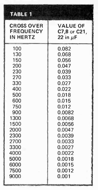

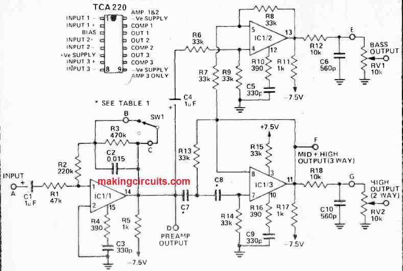
This output is the high range in a 2-way system or the mid plus high of a 3-way system. This signal, when deducted from the input signal by IC1/2 provides the bass range output. A second high-pass filter where C21, C22, R32 and R33 make up the frequency deciding network. They also provide the output for the tweeter in a 3-way system. Once subtracted from the mid-plus high signal, this leaves the mid as required.

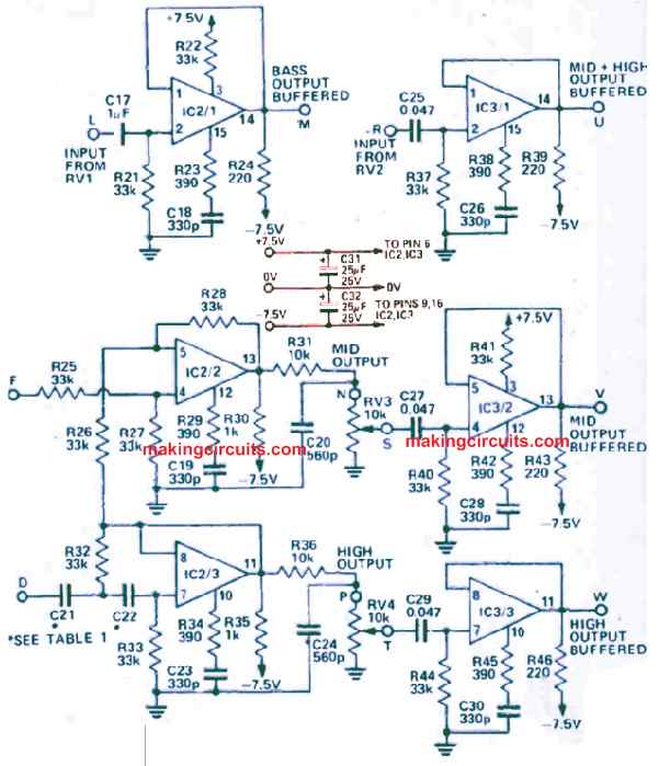
Every output goes to a level set potentiometer and ultimately is buffered by amplifiers IC2/1 and IC3/1, 2, 3. These outputs can drive loads in a surplus of 500 Ω. If you need to use an active 3 -way crossover network to power a constant and known load (one kind of amplifier), the buffer amplifiers can be discarded and the outputs obtained straight from the potentiometers.
Power Supply
The full-wave power supply delivers plus or minus 13 V which is regulated to positive or negative 7.5 V by series regulators Q1 and Q2. At the same time, zeners ZD1 and ZD2 deliver the necessary reference.

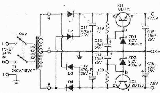
If the unit is to be driven from the power amplifier, C11, C12 and D1 to D4 must be removed. Resistors R19 and r20 are modified to match as depicted in Table 2. The collector of Q1 now travels to the positive supply track of the amplifier and the collector of Q2 to the negative supply track. You must ensure a heatsink is added to Q1 and Q2 if the amplifier supply track is above positive and negative 20 V, or both PCB is being used (buffered 3-way system).
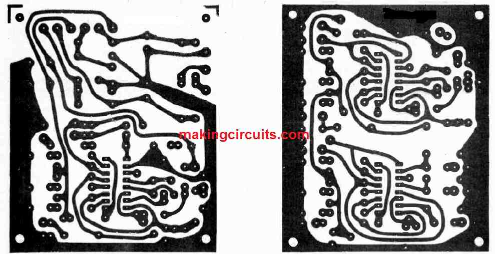
PCB Design