In this article we will discuss about many useful and best alarm application circuits.
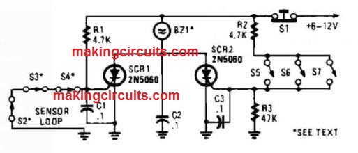
High Power Alarm Driver Circuit
In such a circuit, a less powered SCR is employed to activate" a greater powered SCR. While a switch is opening up (S2, S3, S4) or shutting (S5, S6, S7), either SCR1 or SCR2 activates.
This triggers SCR3 through D1, D2, and R5. BZ1 is a powerful alarm with the continuous sounding sort.


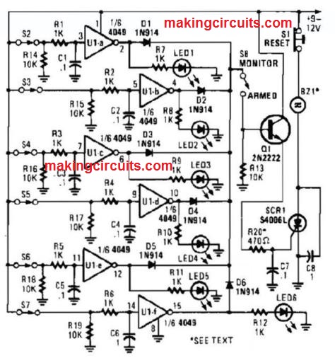
Multi Loop Parallel Alarm Circuit
This alarm has indicator LEDs linked around each inverter output to reveal the indicator of its connected sensor. S8 is utilized to keep track of the switches by way of the LEDS, or even activate an alarm through Q1 and SCRL BZ1 can be quite a ideal alarm in the continuously sounding type.

Series/Parallel Loop Alarm Circuit
A couple of SCRs are recommended along with two sensor loops. One loop employs series switches, another loop parallel switches.
Whenever a switch actuation arises, the SCR activates. The alarm can be a continuously sounding sort.

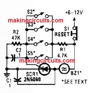
Parallel Loop Alarm Circuit
Four parallel switches are utilized to display four positions. Each time a closure happens on any switch, SCR1 activates, that triggers the alarm.
The alarm needs to be from the continuously sounding type.

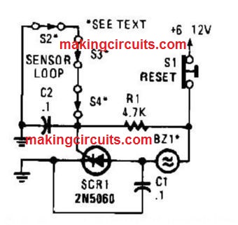
Closed Loop Alarm Circuit
A string of three series linked, generally closed switches are hooked up along the gate of the SCR.
While one starts up, the SCR activates through R1, triggering on an alarm. The alarm must be of the continuously sounding sort.

Delayed Alarm Circuit
The alarm/sensor circuit demonstrated is made around a couple of SCRS, a transistor, a 4049 hex inverter, and also a couple of assist components, all of these incorporate to create a closed~loop detection circuit having a delay function.


The delay function enables you to get into a secured spot and deactivate the circuit prior to the sounder goes off. Hoping how the guarded place is not breached (i.e., S1 is at its usually shut position), while power is first placed on the circuit, a positive voltage is put on the input of U1-a via S1 and R1, triggering its output to go low.
That low is placed on the gate of SCRl, leading to it to stay off. Simultaneously, G6 quickly charges toward the +Vsupply rail via S2, LED2, R4, and D3.
The charge on C6 pulls pin 5 of U1-b higher, triggering its output at pin 4 to be lower. That small is put on the base of Ql, holding it off. Since no trigger voltage is put on the gate of SCR2 (through Q1), the SCR continues to be off and BZ1 would not sound.
However must S1 start, the input of U1-a is pulled low by using R9, forcing the output of Ul-a high, lighting LED1. That higher can also be placed on the gate of SCRl by way of D1 and R3, triggering SCR1 to activate.
Using SGR1 performing, the charge on C6 slowly goes on, the input of U1-b at pin 5 becomes low, forcing its output to go high, decreasing charging C8 via R8 to a voltage somewhat lower than the positive supply rail.
Transistor Q1 stays off till C8 has charged to a level enough to switch Q1 on, permitting adequate time to get into the safe region and turn off the alarm just before it activates.
As soon as C8 has created a adequate charge, Q1 activates and supplies gate current to SCR2 thru R6, triggering the SCR to switch on and activate BZ1.
When the circuit is reset prior to the delay has elapsed, no alarm will sound. The delay time could be extended by increasing the value of either or each C6 and R5; reducing the value of either or each of those elements may limit the delay timer.
Each of the switches utilized in the circuit will be with the usually shut (NC) variety. Switch S1 could be any sort of NC safety switch. Switch S2 could be whether pushbutton or on/off switch.
Simply because S3 is employed to turn off the sounder (BZ1) only, whatever from a button controlled security switch to a concealed on/off switch can be employed.
Door Minder Circuit
This circuit tracks a door to figure out whether it has kept open. Just after 24 seconds, the alarm actives. S1 is a magnetic sensor.


The alarm is an electronic chime audio which is hit one time per second.
Strobe Alert System Circuit
The circuit is triggered by an LED/photorcsistor isolator (U1), that is a blend of the light reliant resistor (LDR) as well as an LED in one package.
That device was selected due to its large isolation (2000 V) feature, which can be essential since the strobe portion of the circuit is instantly attached to the ac line.


The voltage divider is created by just R2, U1‘s in-built resistance, and R3. While U1's in-built LED is off, U1‘s in-built LDR carries a extremely high resistance on the request of 10 MQ.
The voltage placed on NE] is substantially under its ignition voltage of around 90 Vdc. The optoisolator’s internal LED is turned on by the dc signal providing 20 mA.
The external sensor(s) which provide signal are coupled to the strobe section of the circuit at J1 and J2. Once the in-built LED lights, the LDR‘s resistance reduces to about 5 kfl.
Within this situation, around 125 Vdc is utilized across C1, R4, and ()2. The neon lamp regularly fires and extinguishes as capacitor C3 charges via R4, and discharges through NE1 and the SCR gate. Resistor R4 eliminates the current input to C3, and therefore regulates the firing rate of NE1 around thrice per second.
The discharge by means of NE1 is put on the gate of SCR1. SCR1, a sensitive gate unit, snaps on right away when NE1 performs, which finishes the ground circuit for transformer T1 (a 4-kV trigger transformer).
As SCR1 toggles on / off in time using the firing of NE1, capacitor (J2 (linked in parallel with T1‘s primary) charges through R1, and then discharges very quickly via T1 ‘s primary winding.
A voltage pulse is placed on the trigger input of FL1, a Xenon flash lamp. It is essential to understand that the circuit is attached straight to the ac line.
Resistor R6 is incorporated to restrict the level of line current accessible to the circuit. The value of R6 could be lowered if you expect to change the circuit for further flash power.
Caution: However the circuit is fuse guarded, it may be harmful if dealt without any precaution.
Warble Alarm Circuit
This circuit relies on 556 to initially build 21 low frequency square wave, which is regulated to develop a couple of different tones of around 400 and 500 Hz, Circuit creates warble alarm of European emergency vehicles.


The oscillators frequencies are dependant on the values of R1, C1 and R2, C2.
Audio Alarm Circuit
In the circuit, U1 amplifies the sound located through the condenser microphone. Resistor R1 restricts current, Whilst R2 and R3 center the output of the amplifier to 1/2 B+ to permit a single power supply to be employed. Diodes D1 and D2 correct the output of U1, and G3 filters the producing pulsating dc.

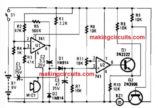
Hence, a dc voltage which is relative for the surrounding audio level is generated That voltage is introduced for the non inverting input of U2.
The inverting input receives a reference voltage of between O and ‘AB+, that is fixed through R11. Provided that the sound level is lower enough to maintain the voltage at pin 3 less than the voltage at pin 2, the output of U2 remains small (around 1 V). Which is adequate to bias'Q1 partly on.
A voltage divider, created through R8/R10 and Q1 (while it‘s somewhat on), stops Q2 from switching on.
Once the audio level is sufficient to develop the voltage at pin 3 greater than the voltage at pin 2, the output of U2 will go high. Which converts Q1 completely as well as drives Q2 directly into saturation.
The piezo buzzer then becomes activated till the power is cut off.
No Doze Alarm Circuit
This circuit releases a deafening tone when the input switch (S2) is simply not reactivated at preset intervals.


In case you go to sleep and skip reactivating the circuit, it can sound till anyone press S2.
Heat Or Light Activated Alarm Circuit
The audio produced by a 555 oscillator could be switched on (triggered) through heat or light.
Which leads to Q1 to carry out transistor W2 (TIP 3055).Q2 (TIP 3055) works as an sound amplifier and speaker driver.


Piezoelectric Alarm Circuit
The alarm works with a set frequency piezoelectric buzzer in addition to the cadmium sulfide (CDS) cell and also both the transistor circuit to get a distinctive impact.

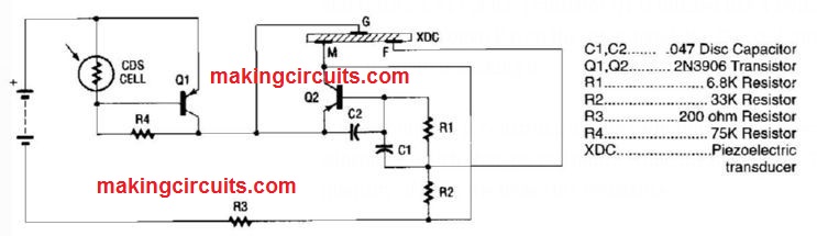
When ever light gets to the CDS photo electric cell, the alarm is muted. But Whenever no light hits the cell, transistor Q1 activates, and the circuit gives out a high frequency tone.
The alarm is made up of piezoelectric disk that oscillates in the preset frequency of 3.137 kHz, developed by transistor Q2, capacitor C1 and C2, and resistors R1 via R3. Transistor Q1 is utilized like a switch. It is forward biased “on” through R4; on the other hand, the CDS cell converts Q1 “off” once the light is striking it.
A CDS photo cell is constructed from cadmium sulfide, a semiconductor substance which changes resistance while the light hits it. The higher the intensity of light, the lesser the resistance.
The lower resistance performs positive voltage for the base of pnp transistor Q1, holding it switched “off” once the light shines within the ODS cell. When the light is eliminated the CDS cell supplies a resistance of above 100 k.
That triggers Q1 to switch “on,” permitting a positive voltage to attain the emitter lead of Q2, Which in turn starts to oscillate. Which after that leads to the piezoelectric element (transducer) to create a noisy signal.
Exit Delay For Burglar Alarm Circuit
Switching on S1 charges C1 to the supply voltage. This biases Q1 on through resistors R2 and R3.

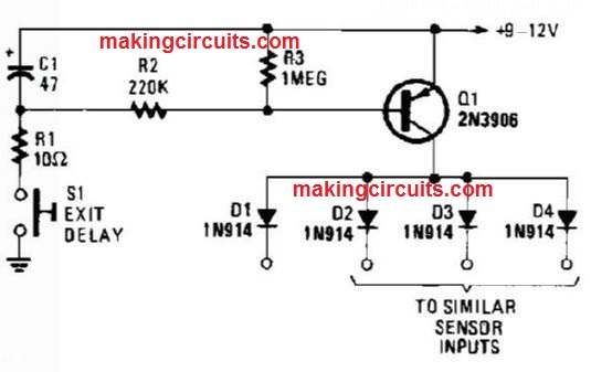
A voltage is obtainable with the time frame from the delay interval, to keep the alarm circuit switched off. C1 could be greater or lowered in value to change the delay periods.
555 Based Alarm Circuit
The alarm circuit incorporates a solitary 555 oscillator/timer (U1) conducting double duty; delivering equally in the alarin trigger circuit and also the entry delay circuit.

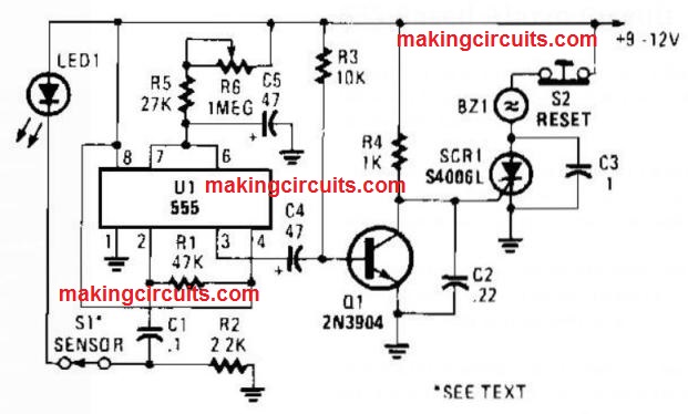
With this application, the activate input of U1 at pin 2 is placed higher through R1. A generally shut sensor switch, S1, comes with a positive voltage towards the junction of R2 and C1, and lights LED1.
Having each ends of C1 connected high, there is not any charge on C1. However when S1 starts, C1 (at first operating as a short) briefly pulls pin 2 of U1 low, activating the timed delay circle.
At the start of the timing cycle, U1 constitutes a positive voltage at pin 3, that charges C4 close to the positive voltage at pin 3, which charges C4 to near to the positive supply voltage, Transistor Q1 is intensely biased on by just R3, maintaining its collector at around ground level. Using Q1 on, SCR1‘s gate is clamped to ground, keeping it off.
Once the delay circuit elapses, pin 3 of U1 will go low and connects the positive end of C4 to ground. Which switches Q1 off. When Q1 switches off, the voltage at the gate of SCR will go positive, switching on the SCR and sounding the alarm.
The delay time is variable from simply a matter of seconds (R6 fixed at its lowest resistance) to around one minute (R6 tweaked to its optimum resistance).
Light Beam Alarm For Intrusion Detection Circuit
Once the light beam which drops on the CDS photocell is disrupted, transistor (EN3904) performs therefore activating SGR1 (G106) and triggering alarm bell. S1 resets the SCR.

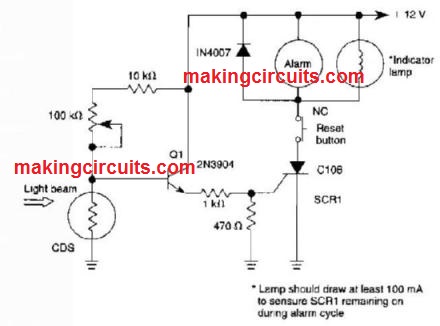
The alarm bell needs to be a self blocking type and electro mechanical.
Light Activated Alarm With Latch Circuit
With this circuit, light triggers R5 to forward bias Q1, R6 determines sensitivity. SCR1 is activated through the emitter voltage on LQ1, activating the alarm bell. While S1 is in the switch on position, SCR1 latch opens.


Make sure that a self-interrupting alarm (electromechanical buzzer or bell) is employed.
Precision Light Activated Alarm Circuit
The photo detector CDS cell R8 designed from a bridge circuit using IC1 as the comparator triggers IC1's output to go high as soon as light hits the CDS cell R8, activating SCR1.


This illuminates LED1 and activates opto isolator IC2, that turns on the load.
Dark Activated Alarm With Pulsed Tone Output Circuit
NOR gates a and b work like a low frequency oscillator which is turned on once the CDS cell, under night times conditions, leads to NOR gate a to get a logic zero at one input.

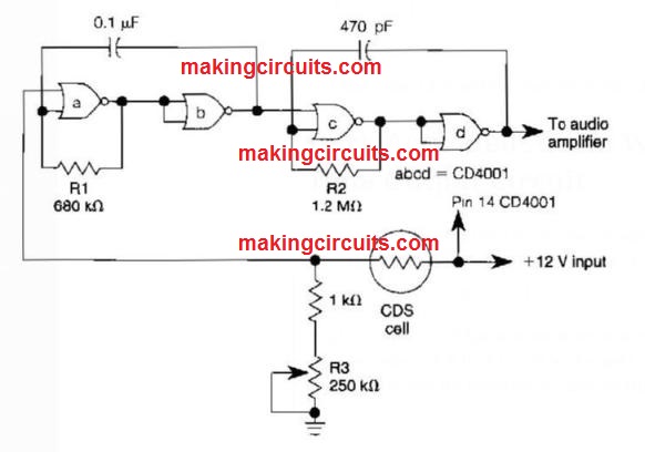
This low frequency (10 Hz) gates a high frequency oscillator (c and d) to oscillate at about 1000 Hz. R1 could be changed to improve the oscillation rate and R2 to alter the frequency. R3 fixes the activation point.
Light Beam Alarm Preamplifier Circuit
This circuit works extremely well for light sources of 20 kHz.The op amp gain is adjusted for a 40 dB gain.


Precision Light Alarm With Hysteresis Circuit
The TL081 is employed for a comparator in the Wheatstone bridge circuit.
Once the CDS cell resistance reduces because of contact with lumination, the output via IC2 trigger the lower frequency oscillator (a) and (b) to create a 10-Hz square wave, pulsing the 1000 Hz oscillator (c) and (d) on / off.


This signal turns an amplifier. R3 regulates hysteresis, that decreases on-off activating close to the limit fixed through R4.
High Output Pulsed Tone/Light Activated Alarm Circuit
This circuit could generate around 1 W of sound power to drive a speaker or horn.


Once the ODS cell is hit through light, its resistance diminishes hence triggering NOR gate (a) therefore leading to (a) and (b) to create a low frequency (10-Hz) square wave.
This triggers the l khz pulses ( c) and (d), activating it to produce a oscillating 1kHz tone in a 10 Hz rate. Q1 and Q2 increase this signal Q2 (2N3055) turns the speaker.
Self Latching Light Alarm With Tone Output Circuit
A reduction in the ODS cell resistance while light hits it triggers latch (a) and (b), which allows tone oscillator (c) and (d) that generates an output of around 1000 Hz. RA fixes the trip level. S1 resets the circuit.


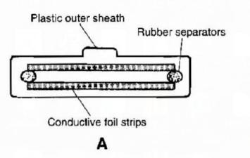
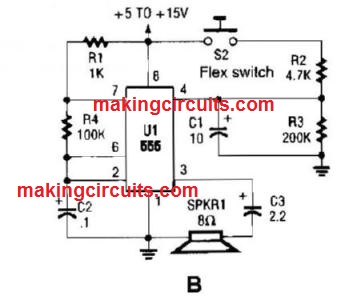
Alarm Sounder For Flex Switch Circuit
This is the cross sectional diagram of a flex switch. They could be employed as pushbutton as well as position detectors.
This diagram exhibits an oscillator, which is often used as an alarm sounder, activated with a flex switch.


Burglar Chaser Circuit
The burglar chaser constitutes a good device for almost any alarm system. It produces amazing flashes of white lumination along with a noisy, annoying audio from the metal horn buzzer.

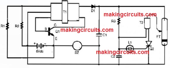

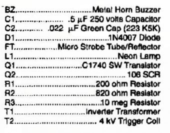
Transformer T1 is linked to Q1, R1, and R2 to make a obstructing oscillator. This leads to a 6-Vac signal around the primary of T1. As a result of T1‘s big turn ratio across primary to secondary, the 6-Vac signal is moved up to amount of above 200 Vac, that is after that fixed via D1.
The resulting dc voltage is placed on filter capacitor C1 and also the neon relaxation oscillator composed of R3, C2, and L1. Whenever C2 charges up to adequate point, it ionizes L1, that leads to SCR Q2 to fire.
The firing SCR triggers the charge on C2 to get placed on the activate coil. The activate coil changes the 200 V in the 4000-V pulse which is required to fire micro xenon strobe tube/reflector FT.
The process repeats itself once the strobe tube flashes.
Silent Alarm Circuit
A sensor switch activates a set-reset flip flop and lights an LED.