

The article explains 7 types of useful antenna circuits which can be applied in various wireless broadcast devices.
Dual-Band Loop Antenna For 80 And 160 m Circuit
This antenna circuit may help to lessen power line noise‘ A plastic “hula hoop” or conduit 3 feet in diameter, coated along with aluminum foil like a shield can be used for L1 and L2.

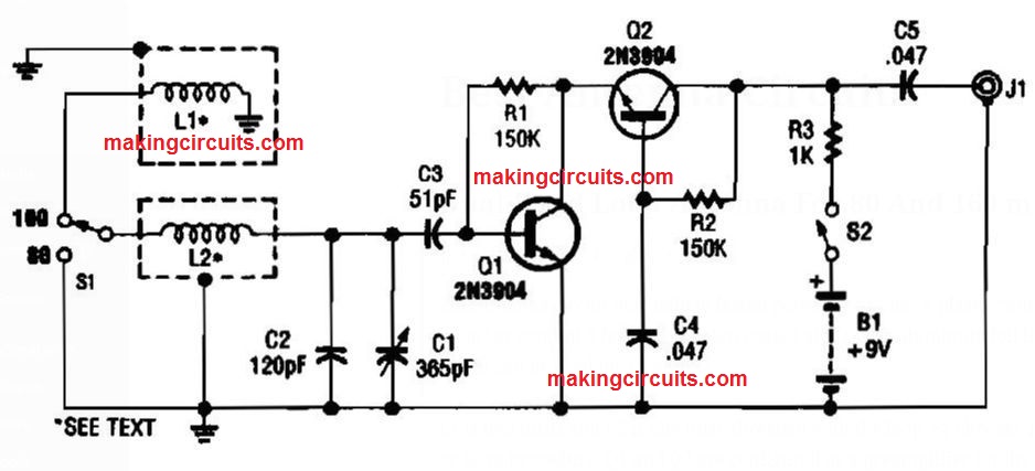


L1 is two turns and L2 is one turn, threaded with the loop. S1 chooses 160- or 80-m procedure. Q1 and Q2 are configured as a preamplifier for the loop antenna. Will not transmit with this particular antenna—it is made for receiving only.
VLF/VHF Wideband Low-Noise Active Antenna Circuit
A 30- to 50-cm Whip antenna supplies reception through 10 kHz to around 220 MHZ. T1, a double gate MOSFET, delivers lower sound, high-input impedance, and high gain.


The circuit is powered by way of the coaxial cable employed to hook up the antenna to a receiver.
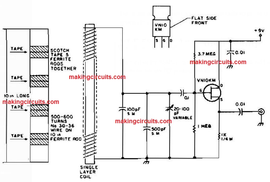
VLF 60-kHz Antenna/Preamp
Appropriate for 60-kHz common frequency reception, listed here is a schematic for any FET preamp and antenna.

Wideband Antenna Preamplifier Circuit
This wideband antenna preamplifier features a gain of about 20 dB via 40 to 860 MHZ, covering the complete VHF, FM, commercial, and UHF bands.


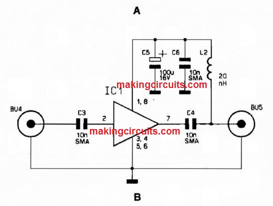
A phantom power supply delivers dc towards the pre amp through the coaxial cable feeding the unit.
HF Broadband Antenna Preamp Circuit
The HF/SW receiver preamplifier is consists of a broadband toroidal transformer (L1~a and L1-b), LC network (made up of a 1600-kHz, high-pass filter and a 32-MHZ, low-pass filter), L2 and L3 (26 turns of #26 enameled wire wound on an Amidon Associates T-50-2, red, toroidal core), a couple of resistive attenuators (ATTN1 and ATTN2), and a MAR-X device.


Demonstrated in this article could be the composition of a simple 1-dB pi-network resistor antenuator. This is actually the technique of supplying dc power to a preamplifier employing simply the RF coax cable.
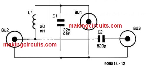
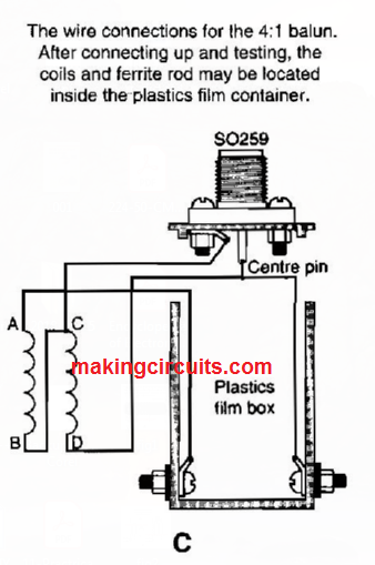
Simple Balun Circuit
An good old ferrite rod from your junked radio receiver could be applied to build an antenna balun as demonstrated.


Loop Antenna Preamplifier Circuit
This preamplifier features a internal regeneration control boost gain selectivity. C1 is a solitary or multi gang AM broadcast band tuning capacitor. L1 is a ferrite loop antenna, tapped at approximately 15 to 25% of overall turns.

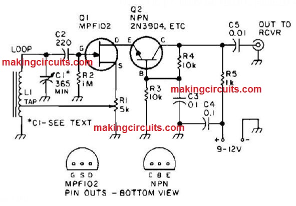
This circuit can prove great for low frequency (up to 3 MHZ) reception, in which a loop could be beneficial to minimize external noise pickup,