


At any time an inductor based load is associated with a DC circuit, including a back EMF protection diode evolves into crucial to be able to preserve the BJT or the mosfet to blame for driving it.
Everyone knows that the same as capacitors inductors have the property of storing and reverting electrical energy across itself. The storing of the electrical energy happens when the inductor is exposed to a potential impact across its leads while the throwing back or discharging the stored electrical energy takes place the instance this potential difference is taken away.
The above described "throwing back" of the kept energy across an inductor or a coil is referred to as as "back EMF"and considering that the polarity of the "back emfs" is actually opposite to the used potential difference turns into a significant threat to the device raised for managing or driving the inductor.
The threat is situated in the point that the reverse voltage inflicted by the inductor makes an effort to create its way by means of the BJT with a reverse polarity leading to a immediate harm to the device.
A basic concept to counter this matter is to add a rectifier diode instantly across the coil or the inductor, where the cathode links with the positive side of the coil while the anode towards the negative.
Such diode set up across DC coils is furthermore known as freewheeling or a flyback diode
Right now at any time the potential across the coil is eradicated, the produced back emfs swiftly discovers its path by way of the diode and gets neutralized other than forcing by means of the driver device.
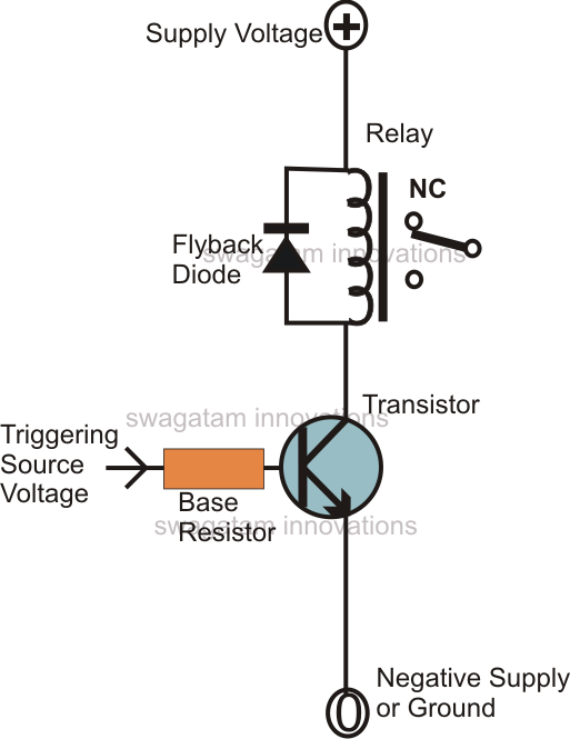
Common illustration of this phenomenon might be observed in a BJT driven relay driver stage, you may have discover lots of these types of in various various circuits. A diode might be usually observed linked across such relay drivers stages, which can be carried out for safeguarding the BJT from the lethal back emfs kicked from the relay coil whenever it's turned OFF by the BJT.

A relay being a pretty small load (high resistance coil), normally a 1 amp rated 1N4007 diode evolves into a lot more than adequate for such applications, in spite of this in situations where the load is comparatively huge or the coil resistance is extremely low, the created back emfs could possibly be comparable to the utilized current levels, which means if the employed current is in the range of 10 amp, the reverse emf would certainly also be around this level.
To absorb such substantial jolts the reverse back emf diode too has to be robust with its amp specs.
Usually, in such instances where the back emf could possibly be above 10 or 20 amps, getting an appropriate single diode turns into hard or very expensive.
A sensible way to counter this is to use many smaller rated diodes in identical, nevertheless since diodes exactly like BJTs are semiconductor devices, don't turn out well when linked in parallel.
The reason being, each diode in the parallel string might have a slightly different turn on levels producing the devices perform individually and the one which switches ON first evolves into accountable of taking on the greatest bulk of the caused current, which itself tends to make the specific diode vulnerable.
Consequently, in an effort to solve the above issue each diode ought to be added with a series resistor, properly determined for the application as per the presented guidelines.
It might be completed in the following manner:
Guess the maximum believed emf current across the inductor is 20 amps, and we choose to utilize four 6 amp diodes as the freewheeling diodes across this coil, suggests that each diode need to share around 5 amp current, the same is applicable for the resistors also, which can be hooked up in series along with them.
Utilizing Ohm's law we are able to estimate the resistors such that they produce minimum safe resistance collectively but singly provides an optimal high resistance forcing the current to share the paths similarly across all the diodes.
Usually a 0.5 ohm resistance is going to be quite secure for preserving the power device, consequently 0.5 x 4 turns into 2 ohms, so each diode may very well be 2 ohms rated.
The wattage with each other ought to be graded for managing the whole 20 amps, for that reason dividing 20 by 4 gives 5, which means each resistor needs to be rated at 5 watts each.


