

The discussed capacitive proximity sensor alarm circuit is composed of a transistor TR1 NPN BC107 (or similar) fitted in oscillator and operating a Darlington TR2 NPN BC517 accustomed to push a 12V relay.
The concept is very easy: TR1 can be an HF oscillator whose frequency relies on the JAF1 choke and also the parasitic capacitance of a metal dish linked to its collector.
The HF developed is extracted from the emitter through the capacitor C3 of 680 pF and ascribed to a couple of diodes
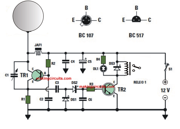
To the silicon DS1 and DS2 that, by aligning it, supply a positive DC voltage.
This particular voltage extends to the base of TR2 that in this manner prospects and excites the relay linked to its collector.
Since the oscillator works around its crucial level, the moment an individual comes near or touches the sensor dish, the oscillator ceases and the base of TR2 is inhibited from receiving positive voltage to maintain per se in conduction, and Ends conducting, which in turn switches OFF the relay.
To place the oscillator in its crucial operating position, an variable capacitor C1 of 60 pF is positioned Between collector and emitter of TR1. DL1, in parallel together with the winding of the relay, runs away anytime the latter stops.
Because the JAF1 choke is 1 mH, a frequency of approximately 500 kHz is attained. By self adjusting the value of this component the circuit functions too, however on another frequency.
To verify the sensor for this capacitive proximity alarm, you can use a rectangle of printed circuit (or a sheet metal, for instance of aluminum) of 10 x 20 cm (smaller it might find hard to prevent the oscillator).
List of electronic components:
R1 = 10 kΩ
R2 = 470 kΩ
R3 = 3.3 kΩ
R4 = 1 kΩ
C1 = 10-60 pF capacitor
C2 = 10 nF polyester
C3 = 680 pF ceramic
C4 = 10 nF polyester
C5 = 100 μF electrolytic
C6 = 10 nF polyester
JAF1 = self 1 mH
DS1 = diode 1N4148
DS2 = diode 1N1448
DS3 = diode 1N4007
DL1 = LED light
TR1 = NPN BC107
TR2 = NPN BC517
RL1 = relay 12 V 1 RT
S1 = switch
(Unless otherwise stated, all resistances
Are 1/4 W at 5%)