The article describes how to prevent corrosion on the detecting probes by employing an IC 555 and a pulsing signal in a basic automobile tank water sensor warning circuit. A dedicated user requested the concept.
Purpose and Needs of the Circuit
On your web page, I was unable to figure out how to submit a project proposal. Perhaps you could assist me with this:
I went through a lot of internet research to find a "No Water Alarm" circuit for my vehicle.
Within the plastic radiator expansion tank, I would like to install a sensor (probes) which can pick up the absence of water and sound an alert.
I can just find water presence warnings or level indicators on the internet. such as flood detectors, rain detectors, etc.
According to my observations, the easiest way to avoid corrosion caused by a DC circuit for the test probes is to use a 555 timer to generate an AC signal that is sent to the probes.
Probes enter the expansion tank.
Circuit configuration
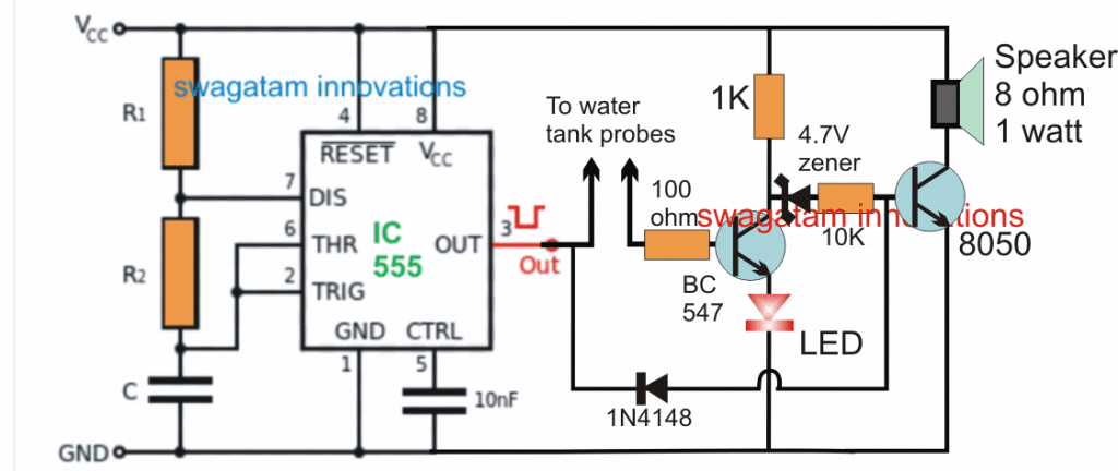
An IC 555 astable design may be used to construct the suggested automobile tank water sensor circuit, as shown in the image below.
In this section we use the idea stated in the query above, even though I'm not entirely sure if a pulsing DC or perhaps an AC signal on the water level sensor probes can stop corrosion in it.
With a frequency that would be able to provide the most desired pitch on the associated loudspeaker, the IC 555 is configured in the design as an astable multivibrator circuit. By changing the numbers of R1/R2/C hooked up at pin #2/6/7 of the IC, this may be tested with.
Cutting the base contact of the transistor attached to pin #3 of the IC produces the pulsing signal needed for the probes within the vehicle's water tank. This transistor stays inactive when there is no water present, allowing the subsequent transistor to conduct and trigger the warning when the automobile tank is empty.
But the first transistor now starts receiving the base bias via probes immediately as the existence of water is recognized since the water bridges over the probes. This indicates that there is water in the tank since it allows the pin #3 transistor to conduct and light up the LED at its collector.
In addition to stopping the speaker tone and forcing the second transistor to cease conducting, this procedure additionally terminates the light from the LED indicating that there is water in the tank.
