

In this post we'll see how to make a simple carbon gauge circuit for measuring carbon emission level of an automobile exhaust system.
Measuring carbon is common usage in the field of transportation. As the world has crowded with increasing number of vehicles plying every day, the increase of carbon has become a major point of contention among the environmentalists. Pollution experts all over the world are constantly warning us of the impending danger on our natural ecosystem. In an effort to manage the killer carbon-effect, the government of various countries are taking stern measure to control this bludgeoning factor. Old cars which have no complied with fuel-emission standards are getting discarded in many parts of the world. The automobile companies are always on a quest to develop some solution to control the carbon-effect.
As a standard process, the carbon-effect of a vehicle is measured by the automobile mechanics, and for which you need to take your vehicle to a nearby garage. While it at times it may seem impossible to take such action because of your lack of time, the best option therefore would be do-it-by-yourself.
This project will describe building a simple electronic carbon gauge that you can use any time as per your convenience to keep check on the carbon factor of your vehicle. Building the carbon gauge is fun and simple.
Here lies below the process of its construction and its circuit diagram by which you can manage the oxide fuel to curb carbon emission.
The diagram n Figure 1.0 illustrates the circuit design of the carbon gauge:
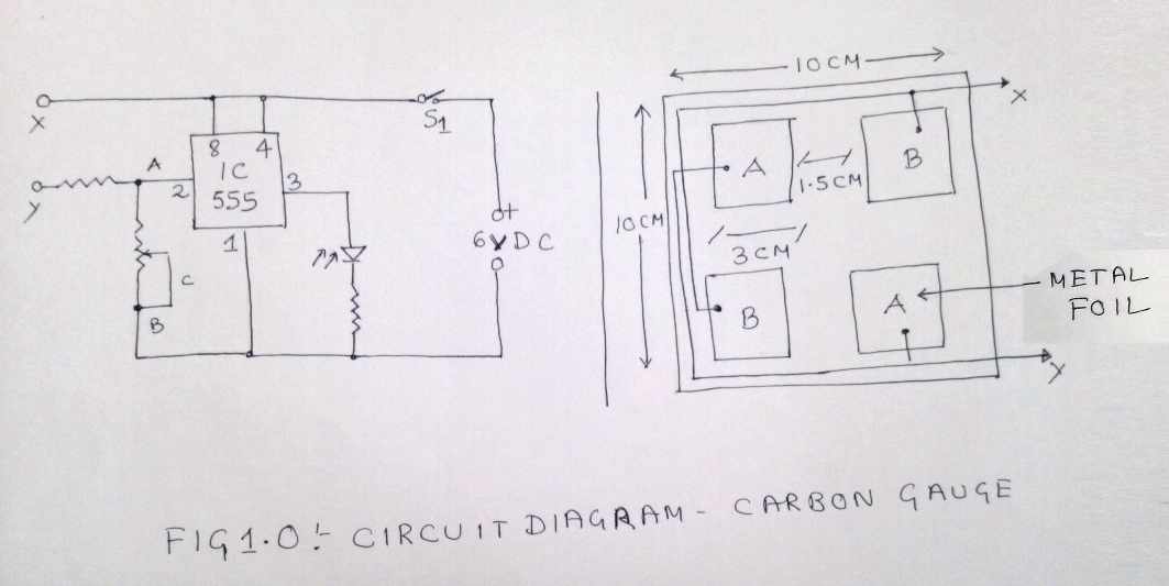

Refer Figure 1.0, the pin 2 of IC1 has a negative connection interfaced via 1M-ohm pot. In this circuit the peripheral device is the screen, made from pieces of copper foil or using four aluminum is connected in the set of two – A and B. They are further fitted on lamination sheet or plastic and the required measurement should follow a size as mentioned in the diagram. Another option is build it as a PCB by applying etching. Set A and B are connected to Terminal X and Y of the circuit.
Carbon Measurement
Maintain a fixed distance and place the metal part of the foil in the screen over the outlet of the silencer. Keep it in the position for at least three minutes and remove. Enable maximum resistance position of the VR1 and initiate the circuit. This will enable the carbon particles spread over the foil to behave like a resistor in between X and Y. Now apply rotation slowly to VR1 towards A where the resistance position is minimum. When the circuit reaches the critical position and IC reaches its optimum point LED1 will light up.