So now, we are talking about one automatic street lamp circuit that is using 4 transistors, right? This thing is very sharp and accurate. Because we put 4 transistor stages then that makes the circuit super sensitive and the switching happens very quickly and precisely. That means that every day, the lamp will turn ON and OFF almost at the same time, no delay, no mistake.
Now this idea was tested and given by "Mr. Ali" who is a serious reader of this blog and also crazy about electronics, right? He sent some images, one shows the circuit drawing very neat and the other one is the board, all assembled properly. So now let us see those and check how it works!

Parts List
| Component | Value / Type | Quantity | Notes |
|---|---|---|---|
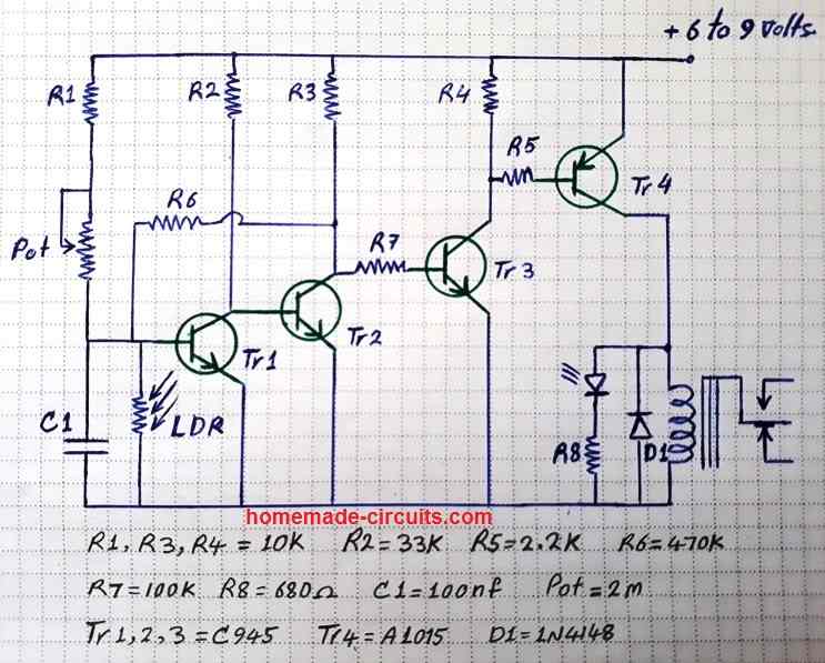
| Transistors | C945 or BC547 | 3 | (Tr1, Tr2, Tr3) Small Signal NPN |
| A1015 or BC557 | 1 | (Tr4) PNP Transistor for Switching | |
| Resistors | 10KΩ | 3 | (R1, R3, R4) General Biasing |
| 33KΩ | 1 | (R2) Sets Sensitivity | |
| 2.2KΩ | 1 | (R5) Controls Tr3 | |
| 470KΩ | 1 | (R6) Works with LDR | |
| 100KΩ | 1 | (R7) Base Resistor for Tr1 | |
| 680Ω | 1 | (R8) Controls Lamp Current | |
| Capacitor | 100nF | 1 | (C1) Stabilizes Circuit |
| Diode | 1N4148 | 1 | (D1) Prevents Reverse Current |
| LDR | Light Dependent Resistor | 1 | Senses Ambient Light |
| Potentiometer | 2MΩ | 1 | Adjusts Sensitivity |
| Lamp / Relay | 6V to 9V Compatible | 1 | Depends on Load Requirement |
| Power Source | 6V - 9V Battery | 1 | DC Supply |
| Miscellaneous | Wires, PCB/Breadboard, Soldering Kit | - | For Assembly |
OK, we have this cheap but very accurate automatic street lamp circuit, right? This one is using 4 transistors to switch the lamp ON and OFF when it gets dark or bright. Let us break it down step by step in a simple way.
How This Works:
LDR and Potentiometer (Pot) Detect Light
The LDR is that thing that checks how much light is around, right?
When there is sunlight then the LDR has low resistance but when it gets dark then its resistance goes high.
The Potentiometer (Pot) is there so we can adjust at what light level the lamp should turn ON or OFF.
First Transistor (Tr1) Senses the Light Change
When it is daytime, then LDR keeps the base of Tr1 low so Tr1 stays OFF.
But when it gets dark then LDR resistance increases and now Tr1 gets a base voltage, so it turns ON.
Chain Reaction Through 3 Transistors (Tr1 → Tr2 → Tr3)
When Tr1 turns ON then it gives a signal to Tr2, making it turn ON too.
Then Tr2 makes Tr3 turn ON.
This way all transistors switch ON one after another like a chain reaction, making the signal sharper and more accurate, step by step.
Final Power Transistor (Tr4) Turns the Lamp ON
When Tr3 turns ON then it activates Tr4, which is the big power transistor.
Tr4 now allows current to pass through the lamp circuit and turns it ON.
The diode (D1) is there to stop any reverse current that could damage the circuit.
During Daytime, Everything Turns OFF
When the sun comes back up, the LDR resistance becomes low again.
This makes Tr1 turn OFF, then Tr2, then Tr3, and finally Tr4 also turns OFF.
The lamp now goes OFF automatically.
Why This Circuit is Good?
Because it uses 4 transistors so the switching is very sharp and quick, right?
The lamp turns ON and OFF at almost the exact same time every day, no delay.
The preset or trimpot is used to set the sensitivity, meaning we can decide at what light level the lamp should activate, as desired by us.
So No microcontroller, no programming, just simple transistor logic, so it is easy to build.
So now, that is how this automatic street lamp circuit works, right? Cheap but very accurate switching!
How to Build
So let us now build this automatic street lamp circuit step by step, right? We will follow an easy way so there is no confusion. Let us start.
Things We Need:
Transistors: 3 × C945 (Tr1, Tr2, Tr3), 1 × A1015 (Tr4)
Resistors: 10K (3 pieces), 33K (1 piece), 2.2K (1 piece), 470K (1 piece), 100K (1 piece), 680Ω (1 piece)
Capacitor: 100nF (C1)
LDR (Light Dependent Resistor)
Potentiometer (2M) – To adjust sensitivity
Diode: 1N4148 (D1)
Lamp and Transformer Setup (Relay-based or directly from the transistor)
Wires, PCB (or Breadboard for testing), Soldering Kit, Battery (6V to 9V)
Step-by-Step Construction:
Get a Small PCB or Breadboard
If we just want to test then we can use a breadboard.
But if we want to make it permanent then we must use a small PCB and solder the components.
Place the Transistors in Line
First take the three light/darkness detector NPN transistors (C945 or BC547) and place them in cascaded format.
Then take the relay driver PNP transistor (A1015) and place it at the end.
Keep space between them so we can connect wires properly.
Connect the Resistors Properly
10K resistors (R1, R3, R4) – Connect them as shown in the circuit.
33K resistor (R2) – Goes between Tr1 and Tr2.
2.2K resistor (R5) – Connect it to Tr3.
470K resistor (R6) – Goes near LDR.
100K resistor (R7) – Connect it before Tr1.
680Ω resistor (R8) – Goes near the output to control current to the lamp.
Connect LDR and Potentiometer
Solder the LDR near the input section where Tr1 is.
Now attach the 2M preset so we can adjust sensitivity later.
Make sure the LDR is placed outside if we are making a final version then it can sense light properly.
Add the Capacitor (C1)
Take the 100nF capacitor and place it near Tr1 and the LDR section.
This capacitor helps stabilize the circuit and prevents false triggering.
Install the Diode (D1)
Solder 1N4148 diode near Tr4, following the correct direction.
This diode protects the circuit from reverse current damage.
Connect the Lamp and Power Wires
Take the lamp or relay circuit and connect it to the output section of Tr4.
If we are using a relay then we must connect the transformer properly so it switches ON and OFF.
Now connect the battery wires (6V to 9V) to the power rails.
Double-Check Everything Before Powering ON
Check that all transistor legs (E, B, C) are connected correctly.
Verify that all resistors and diodes are placed in the right way.
Make sure that there are no loose wires or wrong connections.
Turn ON and Adjust the Sensitivity
Power ON the circuit using a 6V or 9V battery.
Now adjust the potentiometer slowly and see at what light level the lamp turns ON.
If we cover the LDR with our hand then we must check if the lamp turns ON properly.
If we remove our hand then we must check if it turns OFF when light comes back.
Final Setup and Fixing Everything
If everything is working fine then we must solder the circuit properly onto a PCB.
If we are placing the LDR outside then it will sense light properly.
If we are mounting the circuit box near the lamp then we must make sure all wires are properly insulated.
Done. Now the street lamp will turn ON automatically at night and OFF in the morning very accurately without us doing anything.
Testing and Troubleshooting:
If the lamp is not turning ON at night then please try adjusting the preset value slightly.
If the lamp flickers then you must add a bigger capacitor (C1) like 1µF to make switching smoother.
If the circuit does not work at all then we must check transistor connections and make sure the LDR is working properly.
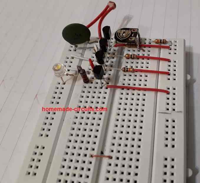
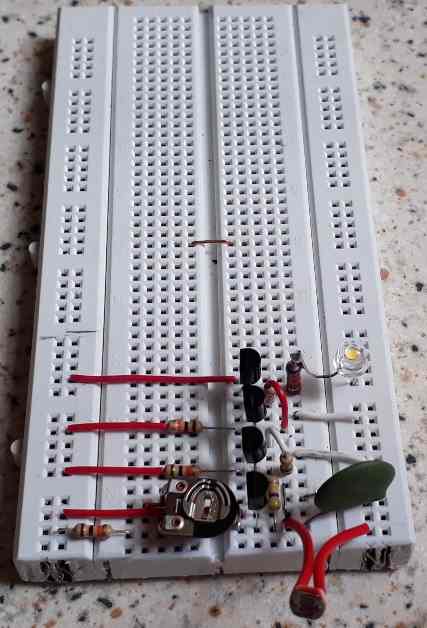
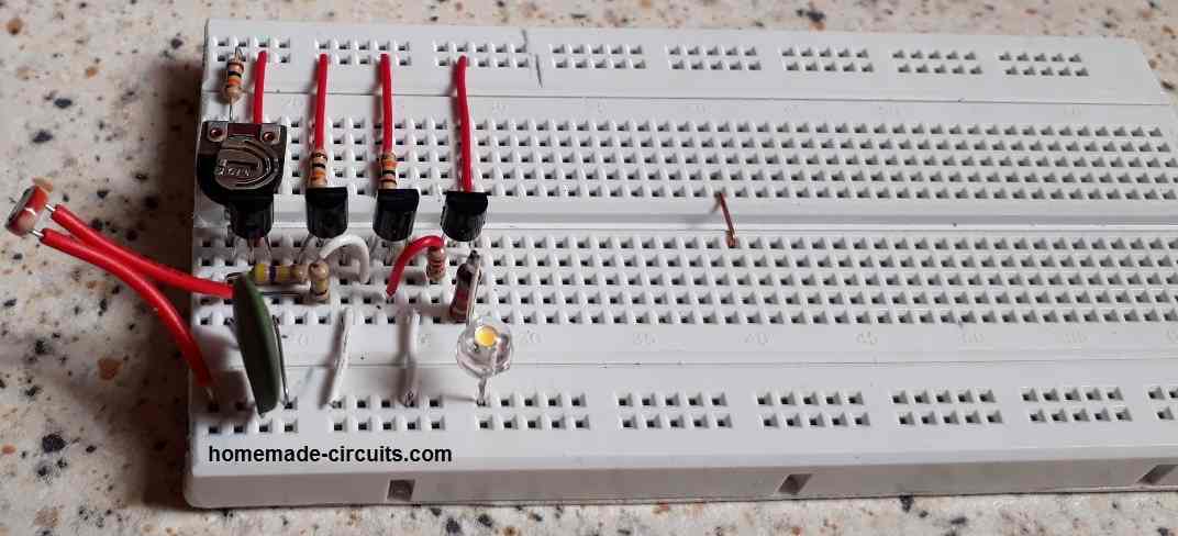
Some Tested Prototype Images