

This High-Gain Current Sensor circuit can be deployed to detect the availability of low-level current flowing though a PCB’s copper lines or traces.
Two straight-pin probes are utilized to form contact with the PCB’s copper trace.
This action diverts a tiny portion of the current from the examined circuit to the current-sensing circuit.

How it Works
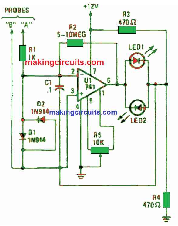
In Figure 1 above, you can see a normal circuit constructed around a lone op-amp.
Voltage detected by the probes is supplied to both inputs of U1 (a 741 op-amp which is set up as an inverting amplifier). This op-amp inverts the input signal and boost it over 1000 times. U1’s output is delivered to two parallel-opposing LEDs namely LED1 and LED2. One of these LEDs will become lit to show current flow and its polarity.
The op-amps output with zero input is configured to half of the supply voltage through R5. The junction voltage of R3 and R4 is also half the supply voltage. That configuration yields a typical bridge circuit with U1 being the arbitrary element and the two LEDs functioning as output gauges.
R2’s resistance dictates the op-amp’s gain whereby for normal use, a 5 MΩ resistor is enough. Still, for detection of lower current levels, R2’s value can be boosted to 10 MΩ for all-out sensitivity.
Diodes D1 and D2 are utilized in the circuit to safeguard U1 from over-voltage inputs. At the same time, C1 is deployed to suppress the circuit’s reaction to AC.
When constructing this PCB current sensor circuit, attach the IC and all other components besides LED1, LED2 and R5 on a tiny piece of perboard. This board can be contained in moderate plastic case.
The LEDs and R5 (which is a null adjuster) must be fixed to one end of the case. You can build the probes using finishing nails connected to the circuit board via short lengths of a hook-up wire.
How to Test
To operate the current sensor circuit, short the probes together and modify R5 to turn of both LEDs.
Locate the circuit-board trace that may have an issue and press the probes hardly on it.
If you notice LED2 is lit, that means the flowing current through the trace in in the direction that generates a positive voltage at probe “A”, which is relative to the voltage at probe “B”. A negative input at probe “A” is true when LED1 turns on.