

In this article we study a neat little LED flasher circuit which could help the bikers and pedestrians, runners, to create a blinking safety light on their body outfit, such as on shirt, belt, shoulders, and use it to indicate the nearby vehicles about their presence in complete darkness, and avoid mishaps or accidents.
The circuit diagram of the proposed nighttime safety light for pedestrians displays the utilization of four NAND gates within the built-in circuit 74HC132
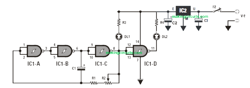

Be replaced by the 74LS132). The initial 3 gates IC1-A, IC1-B and IC1-C are employed in an oscillator level as their frequency is dependent upon the values of C1, R1 and R2, the 3rd IC1-D is attached as a possible inverter to trigger the LEDs DL1 And DL2.
Figure 1: Electrical diagram of the nighttime turn signal for bicycle or pedestrian.
All these integrated circuits working at 5 V and the batteries 6F22 at 9 V getting unquestionably incredibly handy, the voltage is lowered and stabilized by a regulator 78L05.
Simply by switching the knob slider of R2 from one ending of its track to another, the blinking moves from 0.5 to 3 flashes per second.
This blinking darkness safety light circuit for bikers and pedestrians is fitted in a tiny pocket worn as a passing in a belt to place close to its waist (by bike, on foot, etc.).
You will notice that this blinking safety is absolutely great at nighttime.
Absolutely nothing stops more to construct a number of (the cost price is derisory) and to put them in a number of locations such as on shoes, shoulders, helmet, belt, legs etc....or even on a scooter stepney tyre, in order to boost the field of vision.
Parts List
R1 =2.2 kΩ
R2 =10 kΩ trimmer
R3 = 220 Ω
R4 = 220 Ω
C1 = 47 μF electrolytic
C2 = 47 μF electrolytic
C3 = 47 μF electrolytic
DL1 = LED diode
DL2 = LED diode
IC1 = integrated SN74HC132
IC2 = integrated MC78L05
S1 = switch
(Unless otherwise stated, all resistances
Are 1/4 W at 5%)