

The post explains a small DC to DC converter, which can be used for providing an isolated power supply to a specific circuit stage.
We know that if we need to use a digital measuring instrument in association with another electronic circuit, having a different supply for that meter is the better option, maybe even necessary.
You can obviously get two supplies for this, but the same objective can also be accomplished with a single supply using a DC-DC converter. The one explained below is compact and capable of supplying about 50 mA of current.

How it Works
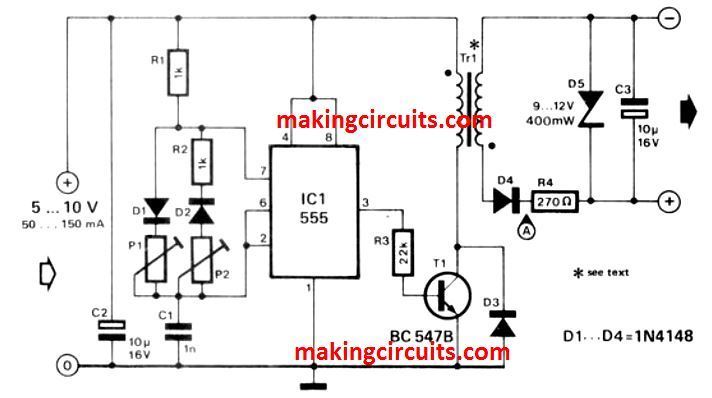
The DC to DC converter circuit is made up of an astable multi-vibrator IC1, the function of which is to switch on or off the voltage supply to the transformer Tr1 through the transistor T1 the secondary voltage of the transformer is half-wave rectified to smooth it, while the D5 zener diode is used to limit the output voltage.
Transformer T1 Details
The ratio of the winding of the transformer used here must be 1:1. The best option here is the firing transformer that you find in thyristors, although the small audio transformers found in pocket radios will also do the job just fine.
You can adjust the converter circuit for its pulse width and frequency to fit the transformer with the help of P1 and P2. The most suitable frequency for the firing transformers is around 100 kHz and that for the audio transformers is in the range 0.5-40 kHz.
Make sure that the transformer is connected with the right polarity. You can calculate the frequency using the formula:
f = 1 / 0.7(P1+P2+R1+R2)
tcharge = 0.7 x (P1 + R1) x C1
tdischarge = 0.7 x (P2 + R2) x C1
High Current DC to DC Boost Converter Circuit
The following circuit is designed to convert this 5-12 V input to a variable 15-30 V output. The converter is based on a Texas Instruments L497A, which is perfect for building a fly-back circuit. A fly-back converter's switching duration is divided into two phases.

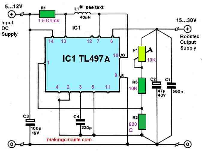
The magnetic energy is contained in an inductor in the first phase, which is connected to the input voltage through a power transistor. The current flowing through the inductor grows in a linear fashion until it reaches a specified peak (here adjusted at 500 MA by R1).
The input voltage is separated from the inductor in the second phase by switching the transistor. The magnetic energy of the inductor is subsequently transferred to an electrolytic capacitor by charging it through a diode.
An oscillator, a current limiting circuit to keep the inductor from saturating, an error sensor which evaluates the output voltage to an internal reference of 1.2 V, and a power transistor with a freewheeling diode are all included in the L497A.
The on-time of the oscillator is determined by C4. The duty factor is adjusted by shifting the oscillator frequency in response to changing load.
The inductor L1 might be a conventional 40 mH, 2 A choke (the value isn't important) that is widely accessible.
To guarantee that undesired voltage peaks are removed from the output, electrolytic capacitor C2 is bypassed by a good-quality decoupling capacitor, C1.
In case the output is used to operate an analogue circuit, a tiny choke may need to be connected in series with it. If the circuit is supplied by a battery, capacitor C3 is required due to the battery's high internal resistance.
The configuration of this sort of circuit, which may experience quite large peak currents, is crucial. Begin by constructing a C1, C2 star junction and the output potential divider.
Take an earth line directly from this junction to the IC's pins 4 and 5. The internal switching transistor's emitter must be linked directly to C3's negative terminal. It is critical that the emitter doesn't really pass through the internal voltage reference's earth return (pin 4).
The max output current is determined by the difference between the input and output voltages, and is usually in the hundreds of milliamperes range.
The output voltage has a fluctuation of roughly 100 mV. (this is always worse in switch-mode converters compared to the linear types).
However, even with variable input voltage, the stability of this DC to DC converter is great. A quiescent current of roughly 8 mA is drawn by the circuit. with an efficiency rate of 75%