

First of all, this project will not seem interesting to every reader. But, this has many possible applications. This is a seven segment display, with a diameter of 280x140mm. The size readily explains that the displays are designed to make alphanumeric information legible at a distance.
This is large LED display can be designed to highlight, for example, score boards, speed indicator, lap counters, digital church clocks etc.
Advantages of Jumbo LED Display
The advantages of these displays are mentioned below-
· They remain entirely in solid state. This prevents segment failure. Because the life of the LEDs is much longer than, for example that of incandescent lamps.
· They do not require intricate reflector constructions.
· Just in case one LED fails, they whole system remains fully legible due to the special segment construction.
· In variety of colors, for instance red, green, blue, yellow, orange the LEDs are being easily arranged.
· With relative high frequency the LEDs work with 24 V - this ensures low heat dissipation.
Disadvantages
Some believe the large number of LEDs required for this display board is a major disadvantage. But this is hugely outweighed by the above advantages.
The seven segment display has been depicted in figure below. It is based on a type 74LS248 decoder.

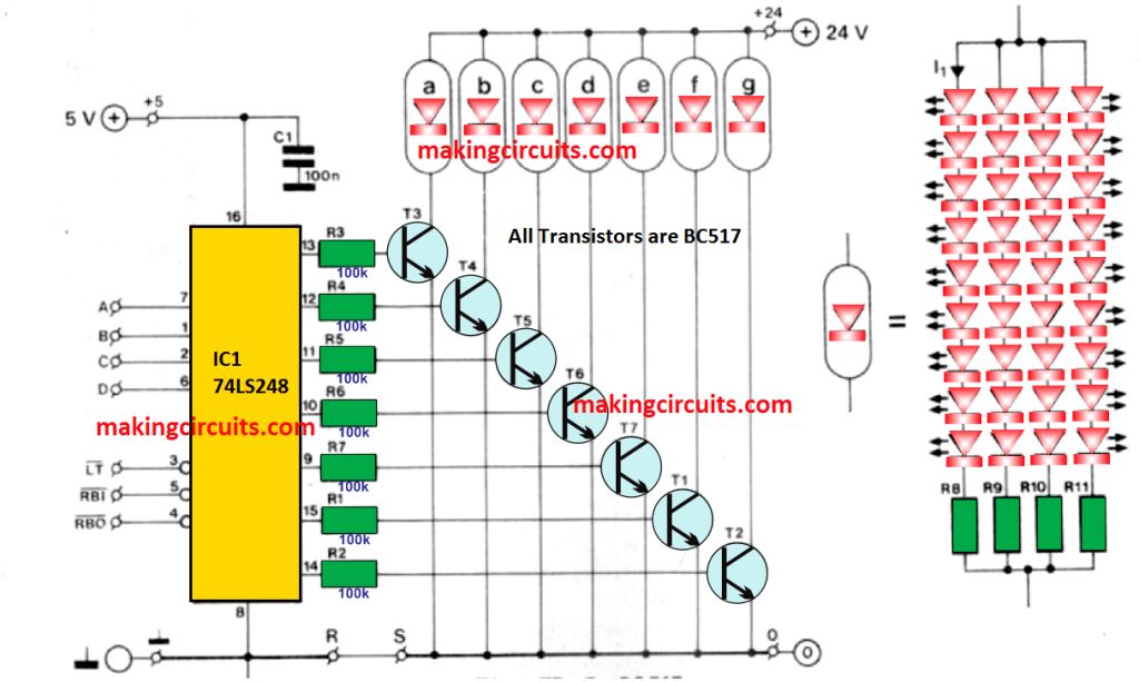
This is the same feature as the well-known type 74LS47/247 decoder. However, the former has in addition internal pull-up resistors, as well inverted output signals – this enables the external transistors to cope with the large currents drawn by the segments.
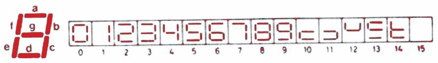
The input as well as the output decoder, the readouts, as well as the additional functions are correlated in the figure shown below.

All inputs and output controls have been arranged external to the decoder. This enables them to be used in the same way as with normal displays. Wire ink R-S serves to interconnect the earths of the +5V and +24V supplies.
There is a switching stage for each segment at the output of the decoder. Each segments switches the relevant segment to turn on or off.
Each segment contains four parallel groups consisting of 8 or 9 LEDs in series along with a current limiting resistor.
The displays can be powered from a non-stabilized 20 to 24 V supply. The current drawn per segment differs from 50 mA to 100 mA.
How the Circuit Works
The following two Figures below give the diagrams for displays with a ‘’1’’ and a “:” respectively. Both can be used as a 12 hours clock.

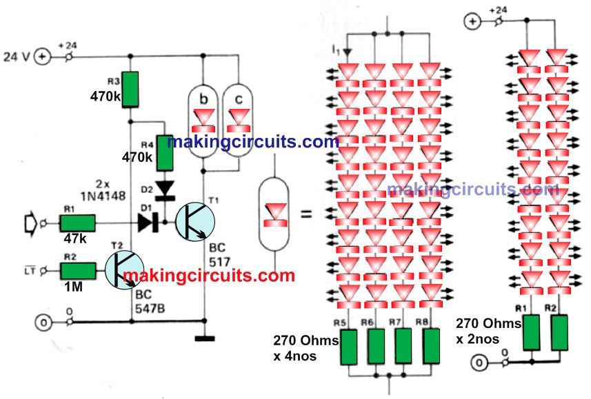
The “1” display has provision for a lamp test (LT); the open inputs are being considered active, that is the display lights.
This is contrasting to the seven-segment display. This treats inputs which are not connected as logic high, that means they are inactive.
As mentioned before, read-out boards contains several figures that may compose by mounting a number of displays side by side on the surface of a flat base.
The whole structure can be protected by translucent red Perspex which also functions as a light filter. This improves the legibility.
Uniformity of diode’s brightness is not so important in this application. Because at the distance for which these displays are intended, no difference in brightness is being observed.