

You can find almost no suspect that desire for this specific circuit increases as the price of electricity - in addition to energy in most cases - is constantly on the rise.
The differential switch has the capacity to measure the difference in temperature among two points and, with respect to the temperature variation, it will eventually switch a relay on or off.
The relay then can be applied, for. instance, to switch on a circulation pump.
There are several applications for the differential temperature detector switch circuit.
It is usually found in combination with solar heating panels or solar collectors therefore it may also usually be accustomed to handle the pump in central heating systems.
In the second option situation, one sensor is positioned within the return pipe while the other is located in the hot water outlet pipe near to the boiler.
When the boiler switches on, a temperature variation is established and the pump also switches on.
The eye-catching feature of this design is always that both the temperature difference and the hysteresis of the unit can equally be arranged on their own, in order that they usually do not influence one another.
Furthermore, the alterations are almost linear, meaning that the potentiometer options could be observed again to provide steady benefits.
A LED has been contained in the circuit to provide a sign of once the relay is in fact on.
The temperature sensors are two LM 335s (National Semiconductor). This IC can be viewed as a general zener diode whose voltage raises by 10 mV per ° C.
For that reason, at room temperature the zener voltage is comparable to: (273 4 20)x lOmV = 2.93 V.
The temperature transducers include calibration connections, which can make it achievable to set the output voltage (at 20 0C) to the value mentioned previously.
In a similar manner, unfavorable variations amongst the sensors can be fixed.
Additionally it is feasible to dismiss the modification input of one of the sensors (by not joining it) and also to alter another sensor to offer the exact same qualities since the first.
This tends to create construction and setting up significantly easier.
The essential operation is as follows: The voltages through the two sensors tend to be straight in comparison by IC2.
Once the temperature - and therefore the voltage - of Z1 gets higher than that of Z2, the output of IC2 moves high lighting LED D2 and triggering the relay through transistor T2.
If potentiometer PI has not been switched completely up, a higher input voltage is needed to work the comparator and the relay will as a result end up being turned on at a higher temperature variation.
There is a possible decrease of around 0.6 V around diode D1.
Somewhere around 100 mV of this stays around PI (the particular voltage fall around P1 are adjustable by way of P3).
The 100 mV compares to about 10° C, so in essence P1 are adjustable over-a array of 10 degrees C.
Sensor Z1 must as a result be 10°C warmer than Z2 with P1 at the lowest setting to be able to stimulate the relay.
As soon as the pump continues to be switched on through the relay, the temperature of the sensor near to the boiler will certainly decrease as a result of flow in the water.
This might make circuit switching by itself off almost instantly.
Undoubtedly, this case is unfavorable and as a consequence potentiometer P2 has been incorporated to modify the level of hysteresis by a optimum factor of 5°C.
Along with P2 placed in the center position the circuit features a hysteresis of 2.5° C.
Because of this if P1 has been set to, say, 50C, the relay is going to be triggered once the temperature variation actually reaches 5°C, but actually will certainly not switch off till the variation in temperature is 50C - 2.50C = 2.S0C.
LED D2 should be a red one with an functioning voltage of approximately 1.3 V.
The supply voltage for the differential temperature detector switch circuit is not really crucial and can deviate by a few volts.
The circuit diagram demonstrates a supply voltage of 12 V simply because relays functioning around this voltage are around every corner.

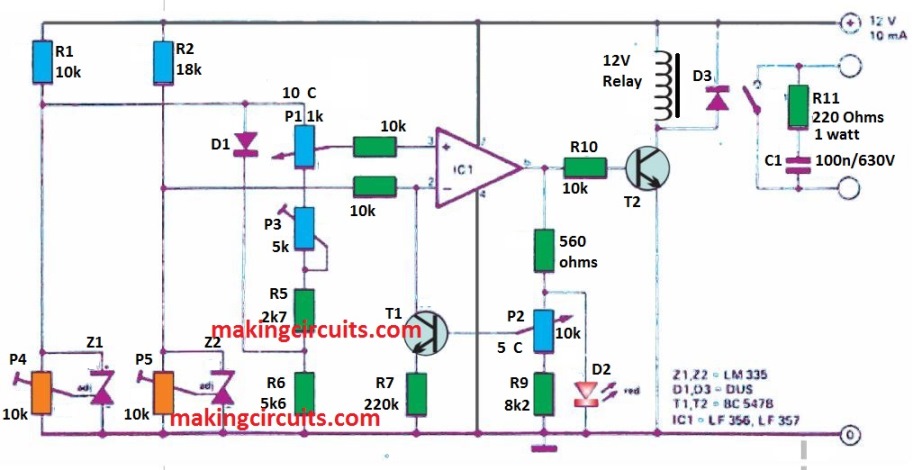
Transistor T2 is merely permitted to dissipate a no more than 100 mA and consequently the current rating of the relay must not surpass this particular value.
Typically the temperature at which the circuit functions could be worked out through the voltage across Z1 and Z2, if a thermometer is not really accessible.