The circuit shown here is based on the switching action of transistors, which produce a digital up/down control of an amplifier volume.
Volume of a stereo deck can be controlled with the help of a potentiometer which changes the resistance between the output of the preamplifier and input of the amplifier.
How the Circuit Functions
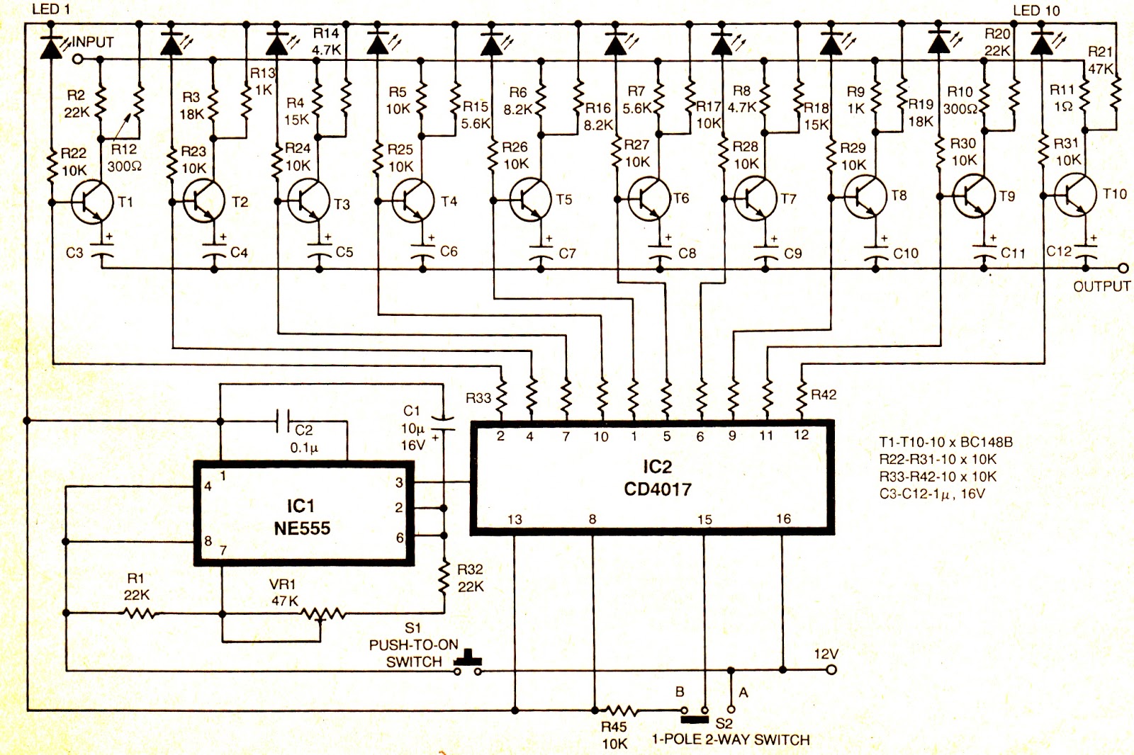
This can be done with the help of decade counter, IC 4017 and some transistors.
The input is applied at collectors and the output is taken from emitters of the transistors.
Depending upon the output of IC 4017, the corresponding transistor gets saturated.
Output from the emitters is taken through a coupling ” capacitor to block the DC components.
When pin 4 of IC 4017 ° goes high, the corresponding transistor (T2) gets saturated and the input signal is directly fed to the output through the collector resistance-:
To start with, press switch S1. The timer IC (IC 555) will start generating pulses at equal interval of time which are fed to IC2.
Depending on the output of IC 4017 the transistor is selected. When desired volume reached; release the switch.
To reset the counter, switch S2 is brought to position A. The time period of the output pulses · can be set, using the formula Td: 0.693 (R1 +2VR1 + 2R32) C1 seconds.
Digital volume controller circuit diagram: