


This post describes tips on how to illuminate a Cree XM-L T6 LED utilizing an existing managed driver circuit while the supply input is from a battery, or in the event a mains SMPS is meant as the driver unit.
The Design
For a battery operated circuit the LED driver could possibly be merely by means of a current controller phase, mainly because here voltage regulation is not crucial and can be eradicated.
According to the Cree XM-L T6 LED driver need to be controlled from a 3.7V/3amp source, with a 3-way switchable dimmer control facility.
The design can be executed making use of the following transistorized current control step. Even though it's not just one of the most economical of the designs, the simpleness gains over the slight inefficiency.
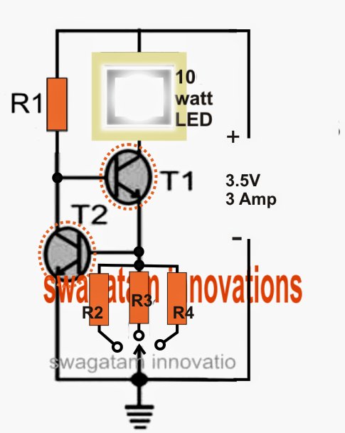
Talking about the above diagram, the design is a simple current controlled stage where T2 establishes the highest current limit of T1 by managing the base potential of T1.
When the circuit is turned on, T1 is activated via R1 lighting the LED. The method permits the whole current used by the LED to go through one of the chosen resistors (R2, R3, or R4) to ground.
This produces a proportionate amount of voltage across this current sensing resistor, which in turn forms the activating voltage for the base of T2.
If this sensed voltage surpasses 0.7V, T2 is forced to trigger and ground the base potential of T1, therefore limiting its conduction, and eventually minimizing power to the LED.
The LED is currently forced to turn off, in spite of this the method as the LED tries to shut off it also starts lowering the voltage across the particular base resistor of T2.
T2 now encounters a loss of initiating voltage and switches OFF, restoring the LED back to its original state via T1, until again the restriction procedure is begun and this goes on, sustaining a current controlled illumination over the associated LED, which is a Cree XM-L 10 watt lamp in this instance.
Right here R4 ought to be picked to permit the LED to light up with optimal intake (max illumination), which may be at its rated 3 amp level....R2 and R3 might be chosen to provide any other preferred lower current operation (lower intensity) to the LED such that by choosing these generates three different intensity levels for the LED.
Parts List
T1 = TIP 41 (on heatsink)
T2 = TIP 31 (on heatsink)
R1 may be calculated by using the following formula:
R1 = (Us - LEDv) x hFe / LED current
= (3.5 - 3.3) x 25 / 3 = 1.66 ohms
Wattage of the resistor = (3.5 - 3.3) x 3 = 0.6 watts or 1 watt
R2, R3, R4 could be determined as:
Low Intensity = R2 = 0.7/1 = 0.7 ohms, wattage = 0.7 x 1 = 0.7 watts or 1 watt
Medium Intensity R3 = 0.7/2 = 0.35 ohms, wattage = 0.7 x 2 = 1.4 watts
Optimal Intensity = R4 = 0.7/3 = 0.23 ohms, wa ttage = 0.7 x 3 = 2.1 watts
To be able to drive the offered Cree LED from an mains managed SMPS, the following measures might be incorprated to be able to implment the needed volatge and current regulated procedures:
1) Procure a 12V/3amp readymade SMPS.
2) Open it and search for the small optocoupler part on the PCB. This may appear like a tiny 4-pin black IC.
3) After you have situated it, change its input side by with care carrying out all the instructins as mentioned in this article post:
Modify and Customize Current inside a readymade SMPS