

Inverters are electrical circuits that convert a DC supply voltage from solar panels or batteries into mains AC supply voltage upto 220 V or 120V and frequencies of 50 Hz and 60 Hz respectively.
The article explains the complete construction procedure for an easy 150 watt H-bridge or full bridge inverter circuit using ordinary P channel and N channel MOSFETs.
The commercial units are known for their compact size, high efficacy and decent power output.
An easier method utilizing a simple mains transformer is however relatively adequate to supply power to a television unit and satellite receiver from a 12 V car battery.
The process of converting an alternating voltage to a higher or lower voltage is done by the transformer.
This is because it delivers decent efficiency and supplies galvanic isolation between the two voltages.
Doing the same from a simple DC source is not as easy as it looks. A circuit which converts DC to AC must be constructed. Only after that, we should decide how to increase or decrease the voltage.
How H-Bridge Configuration Works
Practically, there are two H-bridge or full bridge setups when concerning designs for a mains inverter:
- Direct conversion utilising a 50 Hz mains transformer.
- Conversion involving a switch-mode inverter.
Figure 1 shows the direct conversion configuration where the switching of a low-voltage DC supply occurs through the low-voltage winding of a typical mains transformer.

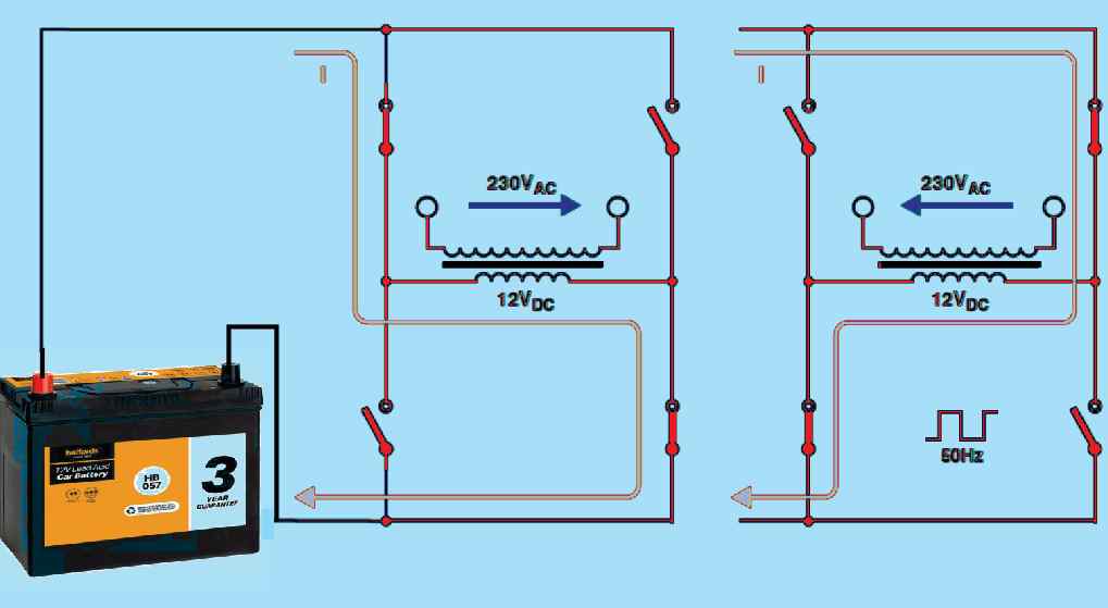
The current is alternately controlled in a single direction and then the other through the winding by the switch configuration. A high-voltage 50 Hz square-wave AC output is generated by a 50 Hz switching signal.
The voltage level is dependent on the ‘turns ratio’ of the mains transformer.
Advantages
The selling edge of this H-bridge circuit is its simplicity where all the electronics are attached to the low-voltage side. However, the main downside is the transformer’s weight and height.
Moreover, inverters which are rated more than 200W are often bulkier and unsuitable for our experiment.
Inverters using the switch-mode configuration as depicted in Figure 2 intersect or change the DC input voltage going through a transformer winding.

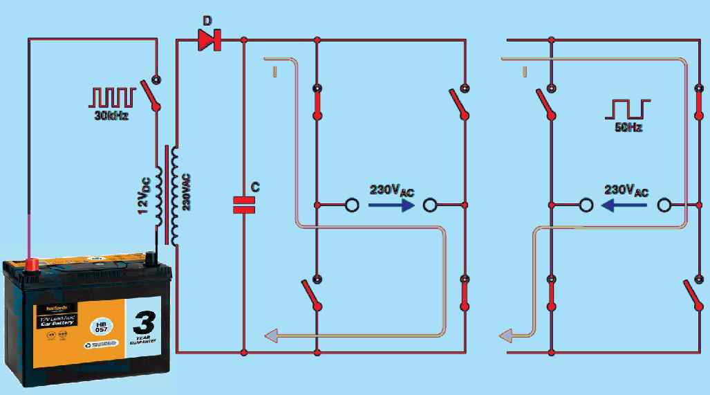
The switching frequency utilized is marginally higher and in the range of 30 to 100 kHz. This permits the transformer design to be extensively smaller and less heavy. The high-voltage output of the transformer also alternates at the exact switching frequency.
Therefore, it is crucial to rectify and then subject the frequency to some complicated electronics like four semiconductors switches in a bridge setup to convert the high-voltage DC into a 50 Hz AC output voltage.
Disadvantages
The disadvantage of this strategy is that the high-frequency (HF) transformer is not a standard one-off the store but must be customized using a ferrite core.
The high-frequency switching waveforms generate significant levels of EMI (Electro-Magnetic Interference) so, to muffle them filters must be introduced. Overall, this kind of inverter is not suitable for novice electronic enthusiasts who want to try building a circuit.
In this experiment, we have suggested using an inverter with a standard mains transformer that is switched by a crystal oscillator with 50 Hz signal. The precision of the frequency warrants that any mains equipment with a built-in clock will sustain good time when driven by this device.
Simple 150 Watt Full Bridge Inverter
Figure 3 below shows the oscillator stage of our 150 watt full bridge inverter circuit diagram and it looks pretty straightforward. The integrated circuit IC1 (74HC4060) functions as a binary counter coupled with an integral oscillator.


There is a crystal with a 3.2768 MHz clock frequency connected across the oscillator inputs. This generates a divided-down rectangular wave signal of 200 Hz at the output Q14 of the counter chip.
Another division operation is performed on this signal by the 74HC112 JK flip flop (IC2) as the second half of this chip divides the frequency into two again, following the first division by the same amount.
A 50 Hz square wave is obtained as a result at pin 5 along with an inverted (phase-shifted by 180°) version at pin 6.
The next disram below depicts the H-bridge of the inverter design configuration that contains four MOSFETs V1 to V4 is constructed with the low-voltage transformer winding creating the central arm of the bridge.

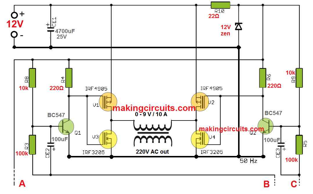
The 3 outputs A, B, C needs to be connections with the above oscillator stage for the required 12V to 220V AC output conversion.
Using 6 V Transformers
Alternatively, you can opt for transformers with two low-voltage 6 V windings where they are connected in series to produce a 12 V winding.
Likewise, a transformer with two independent 12 V low-voltage windings can be applied if these are connected in parallel. What is most important is that you have to ensure the correct phasing of the winding connections.
Capable of reducing their maximum switching rate, power MOSFETs with substantially high input (gate) capacitance of about a few nF are chosen for this experiment.
The H-Bridge driver stage which consists of two transistors Q1 and Q2, each having a low-impedance output, solved the issue with the capacitance and ramped up switching times.
H-Bridge Working
The driver signals to transistors Q1 and Q2 are obtained from the matching outputs (Q and Q) of IC2A. Once the supply battery voltage drops too low, the oscillator can cease operation so that capacitors CE2 and CE3 can supply AC coupling of the control signals to Q1 and Q2.
Then, pull-up resistors R8 and R9 ensure that Q1 and Q2 start conducting. This also forces V1 and V2 which hold the ends of the transformer winding at the same potential to turn off.
Due to this, there is no route for the high current to flow through the winding and MOSFETs.
Output Waveform
As shown in Figure 4, the screenshot of the oscilloscope shows the current and voltage waveforms at the output of the transformer while it is supplying a resistive load like a 100 W mains lamp.

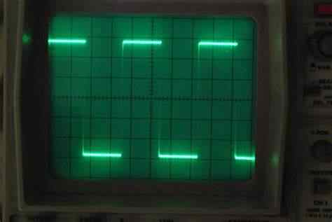
From a 12 V car battery (around 14 V of terminal voltage) which is fully charged, an input current of 12 A produced an output power of of 144.
We measured the power in the load to be 100 W bulb at 215 V and 0.25 A output.
Output Results and Efficiency
The results were more than satisfactory as we achieved 80% operating efficiency which is truly incredible from a simple design.
The losses in the transformer and the switching transistors show that the output voltage does not meet the 230 V level but stayed withing the supply limits of the majority of electrical devices.
You can use an 11 V mains transformer to reimburse for the voltage losses but there are uncommon.
A standard 12 V toroidal mains transformer is flexible and can be modified freely. This type of transformers has the low-voltage winding above the mains winding.
Therefore, you can easily obtain 11 V secondary winding by removing around 10% of the turns.
The MOSFET heatsinks in this experiment permit the application of a transformer with a rating until 150 W. You must use bigger heatsinks if a more powerful transformer is utilized (the MOSFET datasheet shows that they can switch a maximum of 50 A.).
PCB Design
The tiny PCB layout shown in Figure 4 is also simple and straightforward. You have to attach the two-wire links to the board before the remainder of the electronic components is placed.


The ICs can be effortlessly plugged to the board using sockets. Every MOSFET equips its very own heatsink so installing them without any type of electrical insulating gaskets is possible.
But you have to ensure the heatsinks are completely insulated with any other part of the circuit during operation. For connecting the battery with the transformer, two terminal blocks are used, and these must be the properly sized for the cables used.
Make sure that each cable has an adequate cross-sectional area to withstand the input current to the inverter.
Moreover, they must be able to fit an in-line fuse between the inverter and the battery. To operate this easy full bridge inverter circuit up to 150 W, a rating of 15 A is more than enough.