

This solid-state electronic compass circuit employs a one-of-a-kind sensing technology that generates two finely defined points oriented on magnetic north, as displayed by an LED. This allows for a rapid and precise readout. The device, which is enclosed in a plastic container and operated by a conventional 9-volt battery, is compact in size. The battery's usable life is almost equal to its shelf life because the compass circuit is only activated when it is needed to take a readout.
Using Hall Effect Sensors
The creation of a magnetically sensitive solid-state compass is facilitated through a Hall effect sensor, which had been discovered in 1879 by Edwin Hall, who noticed that as soon as a current-carrying gold foil was subjected to a magnetic field, a tiny voltage was formed at the borders of the foil.
Miniature, low-cost Hall-effect detectors are now available thanks to advances in solid-state technology, which are incredibly sensitive and capable of detecting Earth's extremely faint magnetic field.
When no magnetic magnetic field is available, the Hall effect output of the device leads to the formation of a potential difference measured over the breadth of the conducting material, and will be insignificant.
A voltage output roughly equivalent to the strength of the magnetic field is generated when the biased Hall sensor is subjected to a magnetic with the flux perpendicular to the flow of current.
Furthermore, the voltage would be a measure of the angle between the force lines and the sensor's field. When the sensor's front is at direction perpendicular to the planes of force, the optimum Hall-effect output voltage is created, and when the lines of force are parallel to the sensor's surface, zero voltage is generated.
The Hall-effect sensor is additionally improved by adding a reliable, high-quality DC amplifier to the device using integrated-circuit technology. After that, it generates a functional linear output voltage that is sufficiently sensitive to respond to Earth's magnetic field (approximately 1/2 Gauss).
How the Circuit Works
As according the shown schematic, the Hall-effect generators (IC3 and IC4) are three-terminal linear devices that are powered by a stabilized 5 volt obtained from the fixed-voltage regulator IC1. Each sensor's output is a DC voltage that adjusts linearly through a idle value of 2.5 volts as their position relative to the magnetic field's lines of force shifts.

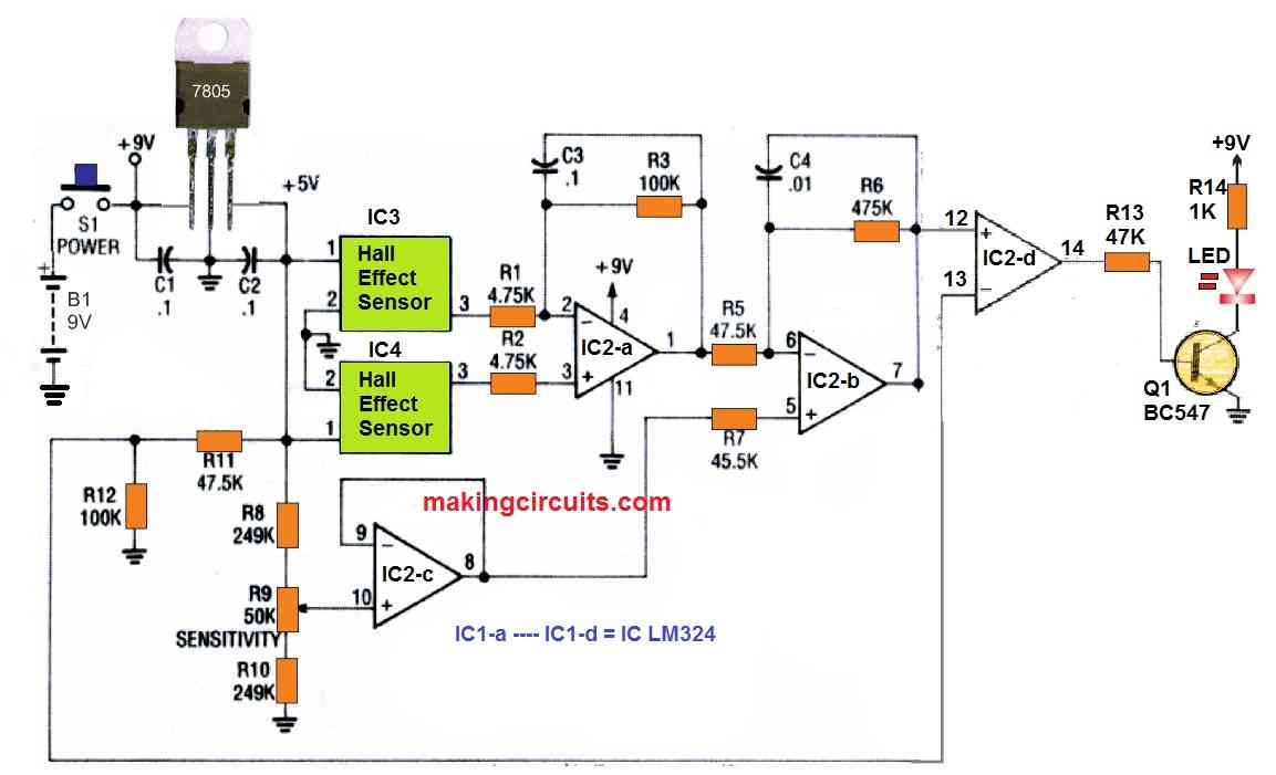
The output - voltage sensitivity of a common sensor is around 1.3 millivolts per Gauss. The circuit employs a pair of Hall-effect generators to deliver double the sensitivity of a single sensor.
As the electronic compass is turned, the output voltage of one Hall sensor will alter in a positive direction while the output voltage of the second hall effect sensor will shift in a negative way. The magnetic field strength and orientation are represented by the voltage difference between the sensors' two output terminals.
The Hall generator's voltage differential is supplied into IC2-a, which is configured as a differential amplifier. Now, while the compass is towards the magnetic north pole, the output of IC2-a (pin 1) will be zero (null), and as soon as it is towards the magnetic south pole, it will be the maximum.
As the compass is rotational, the variation in output voltage of IC2-a is just too small to provide a straightforward technique of detecting the null voltage. As a result, IC2-b is employed as an inverting amplifier through a gain of 100 to boost the voltage difference even further.
The sensitivity-adjust potentiometer R9 and voltage follower IC2-c include a DC off-set that allows the DC output voltage of IC2b to be adjusted to a suitable level for driving the following stage. Using a fixed reference of roughly 3.4 volts provided to its negative input, the op-amp IC2-d is utilised as a voltage comparator.
Once the output of IC2-b sent to the comparator's positive input crosses the 3.4-volt reference point, the output of IC2-d (pin 14) swings high, causing Q1 to be biased forward. LED1 is illuminated as a result of this, indicating that a voltage greater than the reference is present at IC2-b pin 7.
When a voltage comparator is used to monitor a change in the output voltage of IC2-b (pin 7), a couple of clearly defined points are produced, allowing for a much more precise measurement of the magnetic north pole.
How to Test
When you're certain that all of the wiring is in place and working properly, proceed to the verification steps, being sure to utilize a new 9-volt battery. A DC voltmeter hooked up to ground and the IC1 output terminal is required for testing. Verify that the circuit is getting +4.75 to +5.25 volts after powering up the circuit.
Between the 5 volt bus and ground, check the resistance; a typical reading is around 600 ohms. Examine the battery's terminal voltage to ensure that it is supplying at least 7 volts to IC1 while it is loaded.
If required, replace a flat battery. Then, check the voltage range of potentiometer R9 and check the output voltage of IC2 pin 1. (At this point, the direction of the compass is irrelevant.) The voltage must range between 2 and 3 volts DC. Take a reading of the DC voltage at IC2-a pin 1 and write it down.
As the sensitivity control is adjusted over its complete range, note the voltage change at IC2-c pin 8. There must be roughly 0.45 volts differential between the maximum and minimum values.
The midpoint of the observed voltage range must, preferably, be near to the voltage measured at IC2 pin 1 previously. Try adjusting the value of R8 and/or R10 if required such that the voltage range acquired at IC2-c pin 8 is centered around the voltage reading at IC2-a pin 1.
This guarantees that the sensitivity control range for the specific pair of Hall generators utilized in the compass design is correct. Slide R9 across its range while viewing the LED as soon as the sensitivity range is optimal. The LED must be turned out at one end of the configuration and on at the other; if it isn't, verify the polarity of LED1 and the pin positioning of Q1.
As R9 is moved across its range, make sure pin 14 of IC2-d jumps from roughly zero to battery voltage. Verify for a voltage of roughly 3.4 volts on pin 13 of IC2-d, as determined by R11 and R12. Errors in this region might need replacing IC2 if rest of the things appears to be in order; before doing so, double-check your soldering.
When the LED functions as expected, the device is ready to be put to the test under real-world settings. Ensure you don't have any magnetic fields around and that the construction is not concealed by a massive mass of iron or steel before you begin.
Switch ON the supply DC and set R9 carefully so that the LED is just at the switch-over point between on and off while the device is held horizontally in either direction; let at least 10 seconds for the circuit to stabilize.
The LED will flicker when the circuit flips backward and forward. Turn the compass around a 360 degree angle (full circle) after R9 is adjusted, and observe that the LED is on for a portion of the angle and off for the remainder. To get this outcome, lightly tweak potentiometer R9 if required.
The optimal R9 setting would be at the position where the glowing LED arc is as small as feasible. Take notice of the two on/off positions as the compass is turned across the glowing arc. The compass is towards the magnetic north pole while it is midway between those positions, and the scale markings on its face show all other directions.
How to Use the Compass
Before embarking on a compass expedition, make absolutely sure the battery is in good working order and have a spare with you. (A dim or completely dark LED indicates a low battery.) Avoid obtaining a compass measurement in areas where a magnetic field from a nearby gadget could be present, or in places where the Earth's magnetic field is blocked by a large volume of metal.
Keep the electronic compass circuit horizontally and turn it complete circle while keeping an eye on the LED. If the LED is completely on or completely off while the compass is turned, indicates that the sensitivity control has been adjusted. Give at least 10 seconds for the circuit to settle before powering it on.
Except if the circuit is exposed to an excessive change in temperature, the sensitivity control wouldn't need to be readjusted.
Remember that the electronic compass circuit may be used for more than just finding directions. It has an electronic way of determining north, so it should be simple to connect the compass to different devices which need to determine exactly where the north pole is - say, a robot.