


The submit addresses a basic ESR meter circuit that are available for recognizing bad capacitors in an electronic circuit without getting rid of them practically from the circuit board.
ESR which means Equivalent Series Resistance is a negligibly small resistance value that typically turns into an element of all capacitors and inductors and can be bought in sequence with their exact unit values, in spite of this in electrolytic capacitors particularly, on account of aging, the ESR value could continue raising to irregular levels badly impacting the in general quality and reaction of the required circuit.
The creating ESR in a specific capacitor may progressively boost from as low as a few milliohms to as high as 10 ohms, influencing the circuit reply significantly.
On the other hand the above described ESR may well not necessarily indicate that the capacitor's capacitance would certainly also be impacted, the truth is the capacitance value could stay unchanged and good, yet have the capacitor's efficiency worsening.
It is because of this scenario a standard capacitance meter completely is unable to identify a bad capacitor influenced with high ESR value and a technician discovers the capacitors to be OK with regards to its capacitance value which often creates troubleshooting next to impossible.
Where regular capacitance meters and Ohm meters turn out to be completely inadequate in calculating or detecting unusual ESR in faulty capacitors, an ESR meter evolves into incredibly useful for determining such unreliable devices.
An ESR meter enables you to figure out the health of a doubtful capacitor while troubleshooting an old electronic circuit or unit. Furthermore the positive thing about these calibrating devices is that it may be used to measure the ESR of a capacitor without the requirement of eliminating or isolating the caapcitor from the circuit board producing things rather very simple for the user.
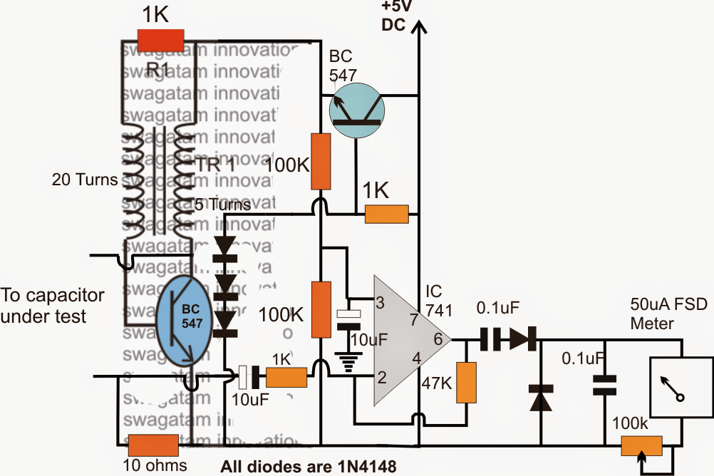
The following figure demonstrates an easy ESR meter circuit which is often developed and employed for the offered measurements.


The circuit might be recognized in the following way:
TR1 together with the connected NPN transistor forms a basic feed back activated obstructing oscillator which oscillates at some quite high frequency.
The oscillations stimulate a proportionate magnitude of voltage across the 5 turns secondary of the transformer, and this caused high frequency voltage is employed across the capacitor in question.
An opamp may also be observed related to the above low voltage high frequency feed and is configured as a current amplifier.
Without any ESR or in the event of a new good capacitor the meter is placed to reveal a full scale deflection showing a minimum ESR across the capacitor which consequently arrives down toward zero for different capacitors owning different amounts of ESR levels.
Lower ESR leads to comparatively higher current to create across the inverting sensing input of the opamp which can be in the same way exhibited in the meter with a higher degree of deflection and vice versa.
The upper BC547 transistor is released as an ordinary collector voltage regulator stage in an effort to function the oscillator stage with a lower 1.5 V to ensure that the other electronic device in the circuit board around the capacitor under test is stored under zero stress from the test frequency from the ESR meter.
The calibration process of the meter is simple. Maintaining the test leads shorted collectively the 100k preset near the uA meter is modified until a full scale deflection is accomplished on the meter dial.
After this, various capacitors with high ESR values might be proved in the meter with respectively lower degrees of deflection as discussed in the earlier section of this post.
The transformer is made over any specific ferrite ring, by using any thin magnet wire with the demonstrated number of turns.