This circuit is utilized to gradually light up and gradually dim a couple of red LEDs (light radiating diodes).
The fading LEDs could be introduced as "eyes" in a little pumpkin or skull as a Halloween fascination, then again mounted in a Christmas tree adornment.
On the other hand, they may be utilized as an extravagant force pointer for your PC, microwave broiler, stereo framework, television, or other machine.
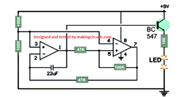
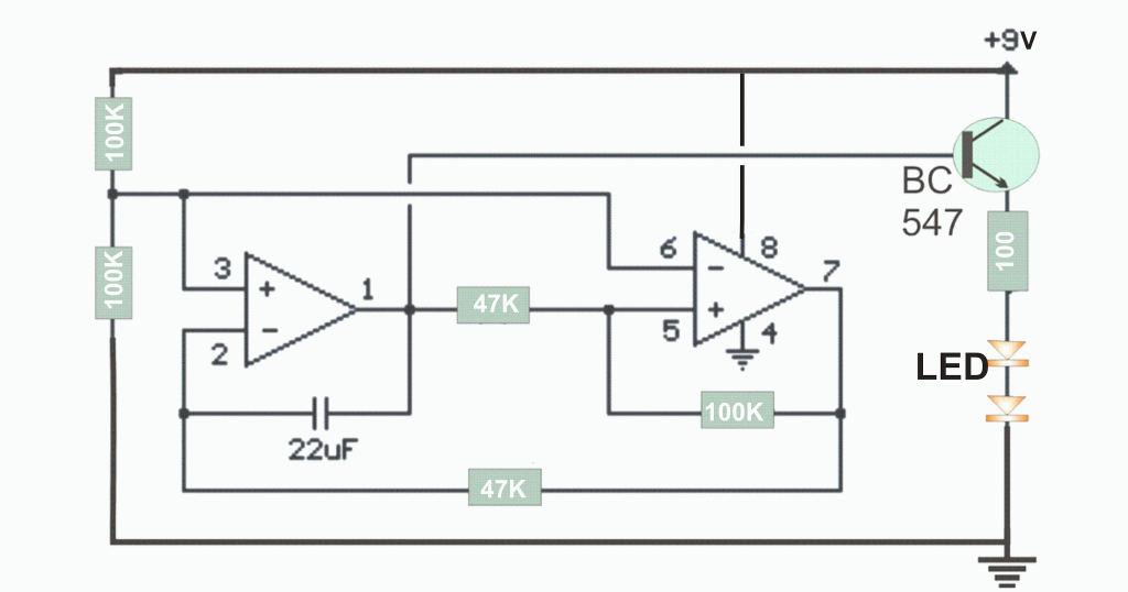
In operation, a straight 3 volt (crest to top) sloping waveform is created at stick 1 of the LM1458 IC and supported with an emitter supporter transistor stage.
How the Circuit Works
The circuit comprises of two operational intensifiers (opamps), one creating a moderate rising and falling voltage from around 3 volts to 6 volts, and the other (on the privilege) is utilized as a voltage comparator, the yield of which supplies a substituting voltage exchanging between 2 and 7 volts to charge and release the capacitor with a consistent current.
The 22uF capacitor and 47K resistor associated with pin 2 build up the recurrence which is around 0.5 Hz.
You can make the rate customizable by utilizing a 100K potentiometer as a part of spot of the 47K resistor at stick 2.
Each of the operation amps has one of the inputs (sticks 3 and 6) attached to a altered voltage set up by two 47K resistors so that the reference is a large portion of the supply voltage or 4.5 volts.
The left opamp is associated as a rearranging enhancer with a capacitor put between the yield (pin 1) and the rearranging data (stick 2).
The privilege opamp is associated as a voltage comparator so that the yield on pin 7 will be low when the info is beneath the reference and high when the data is higher than the reference.
A 100K resistor is joined between the comparator yield and info to give positive criticism and pulls the data above or beneath the exchanging moment that the edge is come to.
At the point when the comparator yield changes at stick 7, the course of the current changes through the capacitor which thusly causes the reversing opamp to move the other way.
This yields a direct sloping waveform or triangle waveform at stick 1 of the modifying opamp.
It is continually moving gradually up or down, so that the voltage on the non-transforming information stays consistent at 4.5 volts.
Conformity to the point where the LEDs douse can be made by adjusting the resistor esteem at stick 3 and 6 to ground.
I found a 56K set up of the 47k demonstrated worked somewhat better with the specific LEDs utilized.
You can explore different avenues regarding this quality to get the fancied impact.
Parts List: Operational amp LM1458 288-1090 1 .48 47K Resistor 296-2182 4 .42 100K Resistor 296-5610 1 100 Ohm Resistor 895-0465 1 .24 Transistor 2N3904 568-8253 1 .1 22uF Capacitor 852-6516 1 .07 Solderless Breadboard 237-0015 1 6.99 Red Light Emanating Diode (LED) 670-1224 2 0.50 Note:
The LED recorded has a thin survey point of 30 degrees and seems brightest when taking a gander at it.
It's not an unadulterated red shading, and a little on the orange side, yet ought to be brighter contrasted with different choices.
Moreover gaps F1,G1,H1,I1 and J1 are all the same association. The external lines along the length of the board are additionally joined together and are ordinarily utilized for power supply associations.
Be that as it may, there is a break in the mid area of the external lines, so a short jumper wire joining the mid area of the external lines ought to be introduced to interface the whole external column together.
Development points of interest: Format of the solderless breadboard: Allude to the drawing underneath the schematic chart and note the solderless breadboard is orchestrated in columns named A-J, and sections numbered 1 to 65.
For a more extensive survey point at decreased power, attempt part number 670-1257 which is perceptible at 60 degrees also, has a red diffused lens. Every gathering of 5 openings in the same section are the same association, so that gaps A1,B1,C1,D1 and E1 are all associated together.
In the event that you have a DMM, utilize the low ohms range and test the different openings to get acquainted with the board design.
Introducing the segments: Orientate the LM1458 so the alcove or punch check on one edge is close segment 30 and the inverse edge is close section 33.
Introduce the LM1458 on the breadboard so the pins straddle the inside area of the board and pin 1 of the IC is possessing opening E30 and pin 8 is in gap F30.
The pins are numbered counter clockwise, so stick 4 will be possessing F33 and pin 5 will be in E33.
Conceivable associations for the LM1458, 9 volt battery, and a few different parts is delineated in the lower drawing of the solderless breadboard, yet it is not finish with all parts.
Allude to the schematic chart, and introduce the different other parts so they interface with the suitable pins of the LM1458.
The board I gathered was associated along these lines: LM1458 F30 to F33, and E30 to E33 22uF capacitor H30 to H31 47K resistor I30 to I35 47K resistor C27 to C31 47K resistor F25 to Positive battery line 47K resistor J25 to Negative Battery line 100K resistor B31 to B33 2N3904 Transistor G36, G37, G38 with emitter at G38 100 Ohm resistor D38 to F38 Driven B43 to B44 (Cathode at B44) Driven I43 to I44 (Cathode at I43) Jumper A30 to Positive battery column Jumper F36 to Positive battery column Jumper J33 to Negative battery column Jumper J43 to Negative battery column Jumper H25 to J32 Jumper J30 to J37 Jumper E27 to G31 Jumper D32 to G32 Jumper D33 to H35 Jumper C38 to C43 Jumper E44 to F44 9 Volt Battery Postive battery column to negative line.
Utilize whatever association gaps are helpful.
Case in point, the 22uF capacitor join between pins 1 and 2 of the IC, which involve openings (F30,F31) so it could be set in the gaps (H30, H31) or (J30,J31) or (I30,I31).
Anyway, not all parts will advantageously fit, so you may need to utilize a short jumper wire (#22 favored) to unite parts from one side of the chip to the next.