

The function of this adsorption type metal detector is to indicate the presence of ferrous and non-ferrous type metals. Its functionality depends on the absorption of magnetic energy.
An inductor remains as a part of a tuned oscillator circuit. This indicator radiates magnetic field. Enough magnetic energy is being absorbed, as soon as a metal object is being introduced into this field; the reason behind this is, the oscillator stops working.
Circuit Description

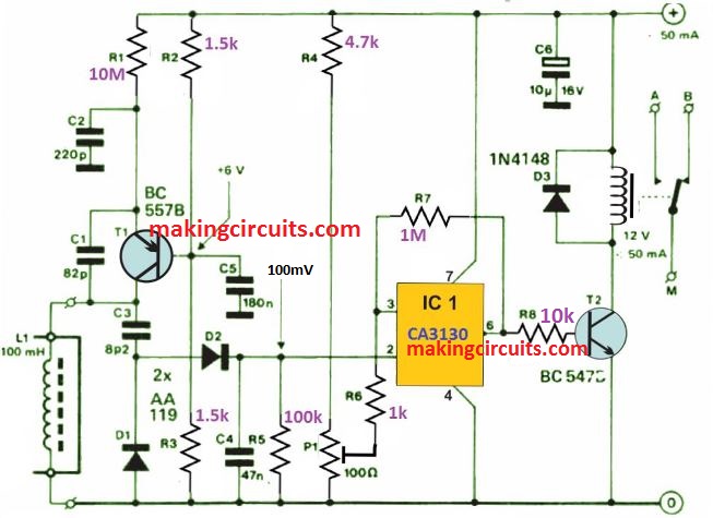
The design of the Colpitt’s Oscillator has been depicted in figure above. This oscillator works at a frequency that is near about 70 kHz. L1, i.e. the inductor also works as the sensor. The Oscillator, R1 only works at the high value of the emitter resistor.
This is a desirable value, otherwise the transistor will replenish any losses in the tuned circuit. D1 and D2 rectify the output of the oscillator. The resulting direct voltage works to the inverting input of Schmitt trigger, i.e. IC1.
However, decrease of that voltage below the desired level at pin 3 (present by P1), the output becomes logic high, therefore energizing the relay.
PCB Design
On a printed circuit board, the ferrous non-ferrous metal detector is best constructed on. This is shown in figure below.

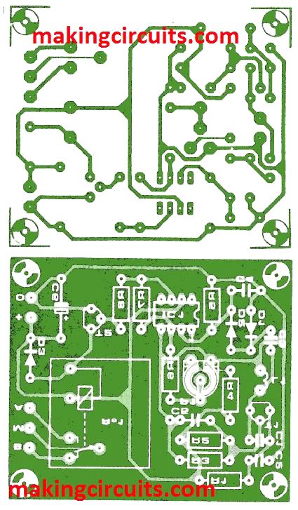
However, it is unfortunate that one cannot get this ready-made. L1, i.e. the inductor is not intended to be set on the circuit board. This is a standard non-screened choke of 100 mH.
How to Test
When the oscillator does not automatically start at setting of P1, the value of R1 has to be reduced to make it work out. However, if the oscillator refuses to stop working when a metal object is placed near L1, R1’s value must be put on higher side, in that case. The stated value of R1 could be found exactly when L1 is of Toko type.
Starting with the wiper of P1 to earth, the present must be adjusted. This will prevent the relay from operating. Advance the wiper a bit further, if it requires a lower sensitivity.
The determination of current consumption is based on if the relay is energized or not. However, it must not be greater than 50mA.