This flashlight remote control circuit can be used to switch ON/OFF any electrical device from a distance by pointing an illuminated flashlight towards the device.
It is sometimes very annoying for a person who, while watching a TV programme or listening to a radio or the like, has to get up to switch lights or fans or AC off.
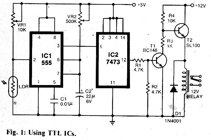
The same applies when he wants to switch them on. Using the simple flashlight remote control circuit shown in Fig. 1, one can switch almost any domestic electrical equipment from a distance, simply by flashing a torchlight.
How the Circuit Works
The basic sensor used in this remote switching mechanism is a light dependent resistor (LDR), whose resistance value changes in response to the incident light.
The 555 timer is used in the monostable mode in Fig. 1, which is triggered when the voltage at its pin 2 falls below l/3 Vcc.
This triggering takes place when light is incident on the LDR, thus lowering its resistance value.
The 10k pot VR1 is used for setting up the triggering threshold. The output time period of the 555 is adjustable up to 12 seconds by varying the 500k pot VR2, so as to smooth up the light impulse (similar to switch debouncing);
The output of the 555 is fed to the input of a JK master/slave flip-flop (7473) which is configured in the toggle mode (by tying the J and K inputs to Vcc).
In the toggle mode, the output of the flip-flop changes state with every pulse at its clock input.
The output of the 7473 feeds an amplifier stage comprising a BC 148 and a SL100 transistor which are used to drive a relay that switches the instrument to be controlled.
The circuit can be mounted on a small veroboard and placed in a cabinet with a small hole for exposing the LDR.
Care should be taken to ensure that the LDR receives only the light from the torch, and that no ambient light falls on it.
Once so installed, it will work reliably, with no false triggering that sometimes occurs in sound operated remote control units.
The entire diagram for the flashlight controlled remote circuit is shown below: