This gas sensor circuit is going to identify just about all pollutants available as gaseous material when it is more than a specific predetermined limits.
Just to illustrate the suggested circuit can be applied for sensing the LPG gas leakage in a your home or the increased signs of CO2 contamination in excessive traffic afflicted zones etc.
It actually can much point out when someone was heavily drunk or intoxicated.
This gas detector circuit presented below is used as a safety measure against the accumulation of excess gas or smoke, which brings with it the danger of explosion or suffocation.
The circuit is created on a TGS 109 sensor which is sensitive to several gases as listed in the table.


How it Works
An 8 V bell transformer is tapped at 5V and used as the power source.
D3 is used to rectify the voltage across the 5 V section, C1 is used to smooth it and R2, D4 and C2 are used to regulate it.
The 5.6 V of direct voltage thus obtained, supplies the IC1.
The remaining 3 V winding in alternating voltage runs the sensor, which needs 1 V at around 0.5 A, while the voltage drop required is provided by R1.
The sensor can be connected both ways in the circuit since the windings on the two sides are identical.
When the gas concentration rises, so does the mutual inductance between the windings of the sensor.
An increased alternating voltage will be observed in the secondary winding of the coil, which must be rectified by D1 and smoothed by C3.
The sensitivity for this is set by P1.
D2 is used to protect one of the inputs of N1 from excessively high inputs.
The buzzer is worked in higher than normal gas concentrations by the gates N1-N2 and N3-N4, which are a stable multivibrators.
Resistor R3 provides protection against changes in sensitivity with temperature.
You can house the detector in a case but the heat dissipation of R1 must be considered.
When the alarm goes off, do not forget to exercise full caution when checking the room.
Another Gas Sensor Circuit Explanation
The presented gas tester circuit could be easily checked by inhaling and exhaling into the sensing unit mouth which could validate its functioning, given that our breathing carries CO2 is going to be instantaneously distinguished by this specific gas sensor circuit.
The resistance (which in neat air is approximately sixty k) will reduce the moment it acknowledges contaminants in the atmosphere.
The CO quantities generally evident in exhaust gases lowers the resistance to under three k.
This significance are very different a tad bit from one sensor to a different and, furthermore, it is actually vulnerable to air temperature, humidity, and standard of heating voltage.
You may currently figure out the place the technical boundaries on measurements with semiconductor gas sensors are situated.
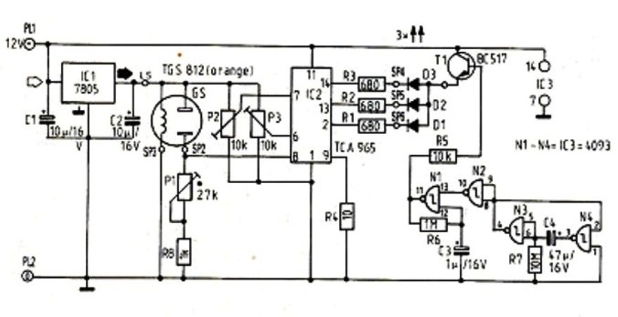
Before studying in depth, it could be advisable to reread the information of the TCA965 window discriminator.
The input voltage to IC2 (pin 8) which can be fixed by P1 goes up with escalating air pollution.
The boundaries of the discriminator, in accordance with one per cent and 4.5% CO amounts respectively, are established with P2 and P3.
With thoroughly clean air, the input on pin 8 can be found below the smaller limit (pin 7): LED D1 (green) illuminates mainly because pin 2 of IC2 is logic ’0’in the collection of 1...4.5 per cent CO, the yellow LED (D2) signals, due to the fact that the input to pin 8 at this point is located within the window.
Whenever the CO amount surpasses 4.5 per cent, red LED D3 illuminates, given that the voltage on pin 8 at this moment is situated over the higher limit (pin 6). Up to now, so much better.
Preheating indicator
The gas sensor needs to be preheated each time before it is applied.
To help you save needing to keep searching for the clock, a little auxiliary circuit functions as flashing indicator lamp.
After the circuit is activated, IC3, along with N3 and N4, makes a low logic intensity for roughly 3 minutes.
Gate N2 inverts this signal to ensure that the rectangular pulse generator in line with N1 turns transistor T1 in tempo with the pulse rate.
After the pre-heating interval has lapsed, the output of N3 turns out high as well as the rectangular-pulse generator is stopped.
While the base of T1 is after that completely at higher logic stage, the LEDs illuminate solid rather than blink.
The pre-heating time frame will depend on R7 and C4, whereas the pulsating frequency relies on the values of R6 and C3.