

In this post we comprehensively discuss regarding how to construct half substracor and full substractors circuits by combining various logic gates
Half subtractor is employed to carry out two binary digits subtraction. In the other articles, we have already reviewed the principles of half adder and a full adder circuit that works by using the binary numbers for the mathematics.
Likewise, the subtractor circuit makes use of binary numbers (0,1) for the subtraction. The circuit of the half subtractor could be designed with a couple of logic gates such as NAND and EX-OR gates.
This circuit offers a couple of features for example the difference as well as the borrow. This post explains half subtractor theory concept consisting of ideas like what is a subtractor, half subtractor with the truth table, and so on.
What is a Half Subtractor?

|
First Digit
|
Second Digit | Difference | Borrow |
|
0
|
0 | 0 | 0 |
|
1
|
0 | 1 |
0
|
| 0 | 1 | 1 |
1
|
| 1 | 1 | 0 |
0
|
In this subtraction, both digits could be depicted with A and B. Both of these digits could be subtracted and offers the resulting bits as difference and borrow.
When you see the initial 2nd and fourth rows, the difference of these rows, and the difference and borrow resemble, simply because subtrahend is lower than the minuend.
Likewise, if we take notice of the third row, the minuend value is subtracted from the subtrahend. Therefore the difference and borrow bits are 1 since the subtrahend digit is higher to the minuend digit.
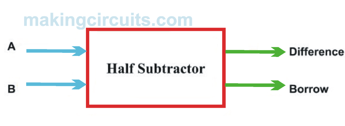
Half-Subtractor Block Diagram
The block diagram of the half subtractor is demonstrated above. It needs a couple of inputs and provides a pair of outputs. Here inputs are displayed with A&B, and outputs are given as Difference and Borrow.
The above circuit could be created using EX-OR & NAND gates. Here, NAND gate could be designed through the use of AND and NOT gates. Thus we involve 3 logic gates for producing half subtractor circuit that are EX-OR gate, NOT gate, and NAND gate.
Blend of AND and NOT gate develop a diverse merged gate called NAND Gate. The Ex-OR gate output would be the Diff bit and the NAND Gate output would be the Borrow bit for the similar inputs A&B.
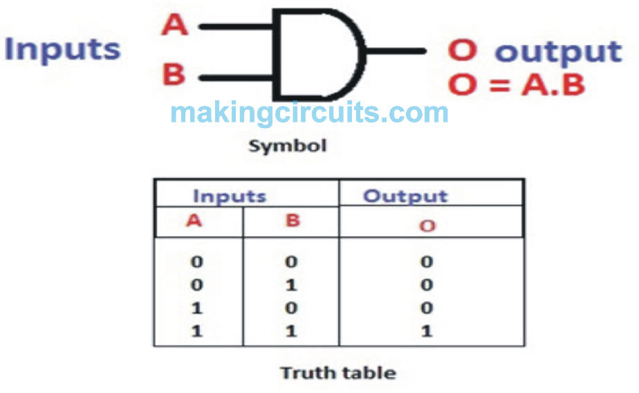
AND-Gate
Whenever all of the inputs of this gate are high, then the output would be high or else the output is going to be low. The logic diagram of AND gate with truth table is displayed in the following image.

NOT Gate
The logic diagram of NOT-gate with truth table can be seen below. Applying this kind of logic gate, we are able to implement NAND and NOR gates.


Ex-OR Gate
If any of the inputs of this gate is high, then the output of the EX-OR gate is going to be high. The symbolic representation and truth table of the EX-OR are given below.


Half Subtractor Circuit using Nand Gate


Truth Table
As an example, if the subtractor possesses two inputs then the resulting outputs are going to be 4.
The o/p of the half subtractor is outlined in the following table that indicates the difference bit and also borrow bit. The half subtractor truth table description can be carried out utilizing the logic gates such as EX-OR logic gate and AND gate operations accompanied by NOT gate.
|
First Bit
|
Second Bit | Difference(EX-OR Out) | Borrow(NAND Out) |
|
0
|
0 | 0 | 0 |
| 1 | 0 | 1 |
0
|
|
0
|
1 | 1 |
1
|
| 1 | 1 | 0 |
0
|

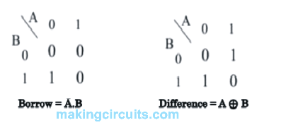
Borrow (B) = x’y
Application of Half Subtractor
The applications of half subtractor consist of the following.
Half subtractor can be used to minimize the volume of audio or RF signals
It may be applied in amplifiers to minimize the sound distortion
Half subtractor can be used in ALU of processor
It could be accustomed to boost and cut down operators and also work out the addresses
Half subtractor can be used to subtract the least significant column numbers. For subtraction of multi-digit numbers, it could be employed for the LSB.
Hence, to sum up half subtractor concept, we are able to visualize that applying this circuit we could subtract one binary bit from another to deliver the outputs like Difference and Borrow. Likewise, we are able to design half subtractor utilizing NAND gates circuit along with NOR gates.
Full Subtractor Circuit Construction using Logic Gates
Typically, the full subtractor is among the most applied and crucial combinational logic circuits. This is a fundamental electronic device, accustomed to carry out subtraction of two binary numbers. In the last article, already we have presented the standard concept of half adder & a full adder that utilizes the binary digits for the computation.
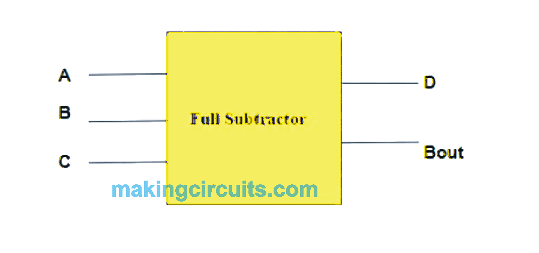
Similarly, the full-subtractor makes use of binary digits such as 0,1 for the subtraction. The circuit of full subtractor could be constructed with logic gates like OR, Ex-OR, NAND gate. The inputs of this subtractor can be a, B, Bin and outputs usually are D, Bout.
This post provides full-subtractor principle concept that consists of the areas like what is a subtractor, full subtractor design with logic gates, truth table, etc.
The information here is helpful for engineering students who are able to proceed through these topics in HDL Practical lab.
What is Full Subtractor?
Full subtractor is actually an electronic device or logic circuit that operates subtraction of 2 binary digits. This can be a combinational logic circuit utilized in digital electronics.


Within the first half-Subtractor circuit, the binary inputs are A and B. As we have talked about in the earlier half-Subtractor article, it will produce a couple of outputs such as difference (Diff) & Borrow.

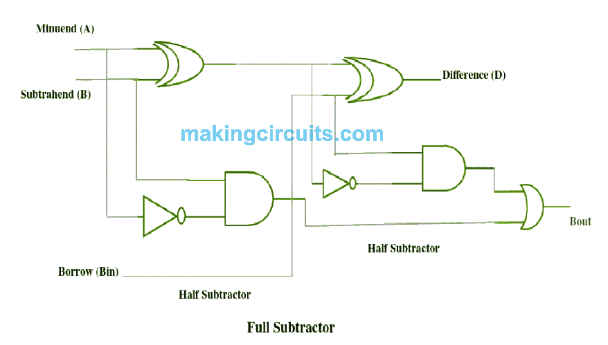
The difference o/p from the left side subtractor is supplied to the Left half-Subtractor circuit’s. Diff output is additionally supplied to the input of the right half Subtractor circuit. We provided the
Borrow in bit across the other i/p of next half subtractor circuit. Yet again it is going to present Diff out along with Borrow out the bit. The end output of this subtractor is Diff output.
Alternatively, the Borrow out of both the half Subtractor circuits is attached to OR logic gate. Afterwards, handing out OR logic for 2 output bits of the subtractor, we get the final Borrow out of the subtractor. The final Borrow out represents the MSB (a most significant bit).
When we take notice of the internal circuit of the full Subtractor, we are able to see a couple of Half Subtractors with NAND gate and XOR gate having an excess OR gate.
Full Subtractor Truth Table
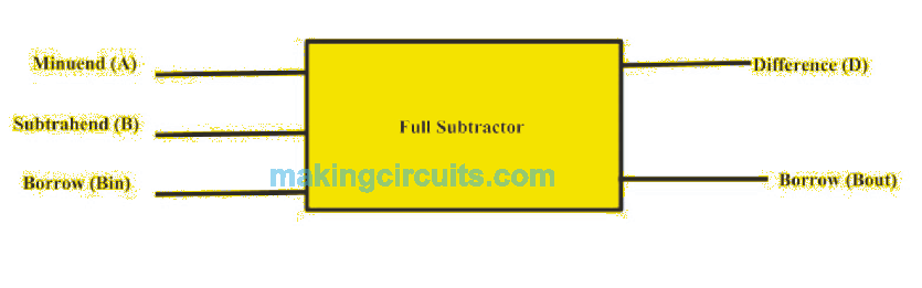
This subtractor circuit completes a subtraction amongst a couple of bits, which includes 3- inputs (A, B and Bin) and 2 outputs (D and Bout).
|
Inputs
|
Outputs | |||
|
Minuend (A)
|
Subtrahend (B) | Borrow (Bin) | Difference (D) |
Borrow (Bout)
|
|
0
|
0 | 0 | 0 |
0
|
|
0
|
0 | 1 | 1 | 1 |
| 0 | 1 | 0 | 1 |
1
|
| 0 | 1 | 1 | 0 |
1
|
|
1
|
0 | 0 | 1 | 0 |
| 1 | 0 | 1 | 0 |
0
|
|
1
|
1 | 0 | 0 | 0 |
|
1
|
1 | 1 | 1 |
1
|
Full Subtractor K-Map


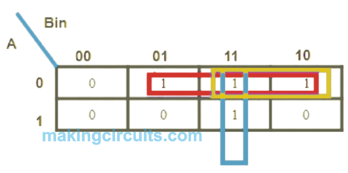
The full-subtractor expression for Borrow is,
Applications of Full Subtractor
A few of the applications of full-subtractor consist of the below
These are typically utilized for ALU (Arithmetic logic unit) in computers to subtract as CPU & GPU for applying in graphics to reduce the circuit complexity.
Subtractors are mainly intended for carrying out arithmetical functions such as subtraction, in electronic calculators and also digital equipment.
These are additionally pertinent for various microcontrollers for arithmetic subtraction, timers, and program counter (PC)
Subtractors are applied in processors to work out tables, address, etc.
It is usually great for DSP and networking based techniques.
To sum up, by analyzing the adder, full subtractor using two half subtractor circuits, and its listar methods, anybody can observe that Dout in the full-subtractor is precisely identical to the Sout of the full-adder.
The sole differentiation is the fact A (input variable) is accompanied in the full-subtractor. Therefore, it is possible to convert the full-adder circuit into full-subtractor by simply matching the i/p A before it is presented to the logic gates to build the last borrow-bit output (Bout).
By employing any full subtractor logic circuit, full subtractor through NAND gates and full subtractor applying nor gates could be executed, because both the NAND and NOR gates are addressed as universal gates. What follows is a question for yourself,
- what exactly are universal logic gates?
- what is the distinction between half subtractor and full subtractor?