

The car headlight reminder circuit can be used to warn the driver that he has left the car's headlight switched on after leaving the car.
You then are up for charging the battery, tow starting, apologizing to the controlling director having merely waited two hours to talk about the future with the company, placating uptight parents whose daughter you have returned soon after they noticed it had been now daylight, or no matter what blend of situations are least beneficial for your instant circumstance.
To prevent this sort of problems is actually comparatively simple and numerous circuits happen to be posted that supply an audible caution when the ignition is turned off even though the headlights or sidelights continue to be burning.
Most of these circuits are usually simple and efficient however almost always are not able to cater to all those events whenever one needs light to be on whilst the ignition is turned off.
In this article then is a somewhat more complicated circuit that delivers a 'headlight on ignition off' caution since the driver opens a door to depart the car.
The alarm stops when the driver shuts the door. As demonstrated in Fig. 1 the circuit is appropriate for vehicles with a negative ground electrical system.


For converting the circuit for employ with positive ground vehicles substitute the 2N3905 with a 2N3904 (the connections are similar) and alter the polarity of the diodes and the 25 uF capacitor.
Figure 2 displays the way the standard circuit is wired into the car's electrical system. The alarm device might be a buzzer, bell or perhaps a blinking light.

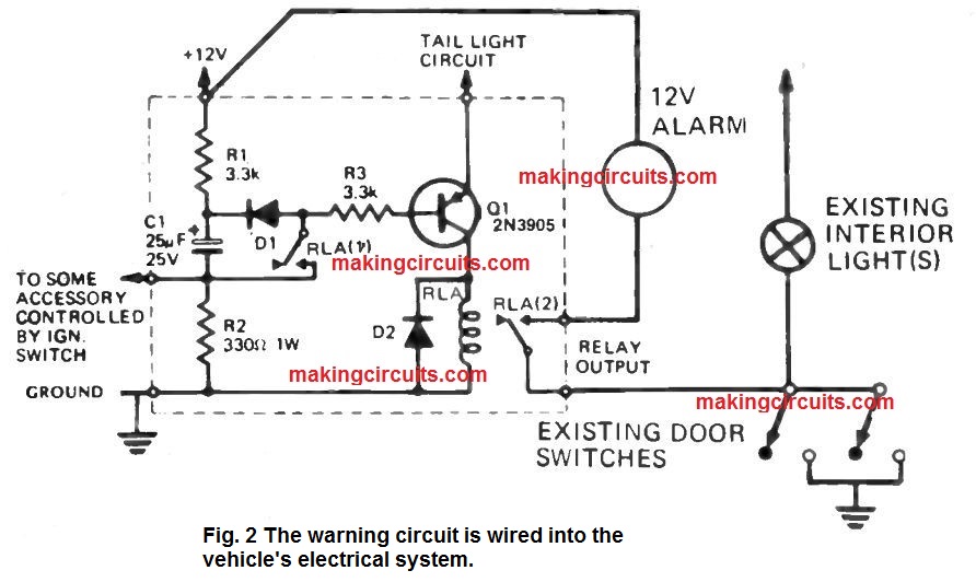
The present door controlled interior light is employed to increase a ground to the relay as a result obviating the need to set up any extra switches. The terminal marked 'tail light circuit' needs to be attached to the live side of the tail light wiring.
(If a headlight just warning is needed, this particular lead needs to be attached to the live side of one of the headlights).
Further more leads link the unit to ground, the 12V vehicle supply and tot he live side of any equipment which is connected from the ignition switch.
How the Circuit Works
Usually capacitor C1 is released through R1 and also the closed switch contacts of an accessory wired through the ignition switch.
In case the ignition is currently turned off, C1 charge quickly through R2 hence creating a negative going pulse at the base of transistor Q1.
If the vehicle's headlights (or side and tail lights) were turned on at the moment, this pulse will switch on Q1, and shut RLA.
The relay contacts RLA (1) and RLA (2) now activate and contacts RLA (1) link the base of Q1 to ground through R2 and R3 as a result evoking the relay to 'latch on'.
If either vehicle front door is opened using the relay in the latched situation a ground will probably be expanded towards the audible alarm device by way of the now closed contacts of RLA (2) and the closed door light switch.
The audible alarm will certainly stop instantly the door is reclosed. Q1 will of course be stop and the relay reset once the lights are switched off (hence eliminating the positive voltage through the emitter of Q1).
If anytime it is needed to turn off the alarm circuit all that is essential is first turned off the ignition to switch off the lights after which on again.
The headlight reminder warning circuit will certainly return to the status quo next time the ignition is turned on.
Car Headlight ON Reminder Circuit
Lots of circuits to alert car owners regarding their car headlights switched on after turning the engine off have seemed during the past.
I believe this car headlight ON reminder circuit can be an enhancement over a number of these for the reason it needs no switches, and it's also just essential to create three connections to the car's electrical system.

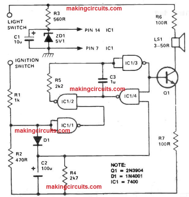
When the ignition is turned off as the lights are on, an audible alarm is sounded for around ten seconds.
This sound is generated by NAND gates IC1/2, IC1 /3 and IC1/4. Procedure of this oscillator is blocked through an '0' on the gating input of IC1 /2.
As a result equivalent to a logic '1' existing at the input to IC1 /1 whilst the ignition switch is on, providing a high logic level to IC1 /1, the oscillator is therefore shut off.
Once the ignition is turned off, the output of IC1/1 will go higher, permitting the oscillator.
At this point C2, which has up to now been charged up through D1, starts to release via R4.
As the voltage across C2 is high, the gating input of IC1 /4 enables oscillator functioning,even so as C2 discharges, this process is stopped.
This takes place after around ten seconds. Power to the car headlight ON reminder circuit is supplied by R3 and ZD1 through the vehicle's 12 V battery.