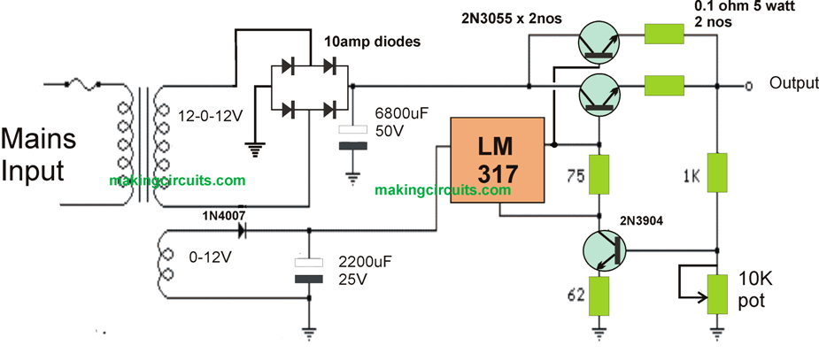
The high current LM317 power supply circuit shown down the page makes use of an supplemental winding or possibly a independent transformer to deliver power to the LM317 regulator in order that the outboard pass transistors are able to work nearer to saturation and strengthen efficiency.
To get decent efficiency the voltage with the collectors of the a pair of parallel 2N3055 pass transistors needs to be near to the output voltage.
The LM317 takes a few added volts on the input side, as well the emitter/base drop from the 3055s, and also no matter what is shed along the (0.1 ohm) equalling resistors (1volt at 10 amps), therefore a different transformer and rectifier/filter circuit is employed which adds some volts more than the output voltage.
The LM317 will supply more than 1 amp of current to push the bases of the external power transistors and with an approximate gain of TEN the combo ought to provide 15 amps or even more.
The LM317 constantly works using a voltage variation of 1.2 between the output and adjustment terminals and demands a minimal load of 10mA, hence a 75 ohm resistor has been picked that will probably bring (1.2/75 = 16mA).
This exact same current runs via the emitter resistor of the 2N3904 which will create around a 1 volt drop over the 62 ohm resistor as well as 1.7 volts on the base.
The output voltage is scheduled using the voltage divider (1K/560) to ensure that 1.7 volts can be ascribed to the 3904 base once the output is 5 volts.
With regard to 13 volt procedure, the 1K resistor could possibly be altered to approximately 3.6K. The regulator is without output short-circuit protection therefore the output most likely must include a correctly rated fuse.