The transformerless power supply circuit illustrated below can offer large current at any fixed voltage level thanks to its straightforward design. The concept appears to have resolved the issue of obtaining high current from capacitive power supply, which at first glance appeared to be a challenging task.
Overview
In this blog post, I've covered a few transformerless power supply circuits that work well for low power applications but lose their effectiveness or usefulness when exposed to large current loads.
The aforementioned idea uses high voltage PP capacitors to lower the mains voltage to the necessary scale, but it it cannot increase the level of current to meet the needs of every application.
However, the current could be increased simply by connecting additional capacitors in parallel because it is precisely corresponding to the reactance of the capacitors.
Nonetheless, this increases the possibility of large early surge currents, that could immediately damage the connected electrical circuit.
Increasing Current by Including Capacitors
Capacitors may therefore assist to raise the current specifications of such power sources, but in order to make the circuit workable for real-world applications, the spike factor needs to be addressed first.
Ideally, the circuit of a high current transformerless power supply described here minimizes the surge caused by power transients to ensure that the output is safe and supplies the necessary current supply within the rated voltage thresholds.
Except for the triac and zener network, which functions as essentially a crowbar arrangement and serves to ground whenever it exceeds the rated voltage, everything in the circuit is maintained just as it was in its previous iteration.
Without the risk of any unintentional voltage or current incursion, the output of this circuit should be able to supply a steady voltage of about 12+ volts at about 500 mA of current.
WARNING: ADADEQUATE PRECAUTION IS NEEDED AS THE CIRCUIT IS NOT DETACHED FROM MAINS AND Thus CONTAINS A HIGH Danger OF ELECTROCUTION.
Parts List
- R1 = 1M, 1/4W
- R2,R3 = 1K, 1/4 WATT
- C1----C5 = 2uF/400V PPC, EACH
- C6 = 100uF/25V
- All DIODES = 1N4007
- Z1 = 15V, 1 watt
- TRIAC = BT136
Update
A more thorough examination of the circuit revealed that the triac was managing the current and limiting the surge while discharging a substantial quantity of current.
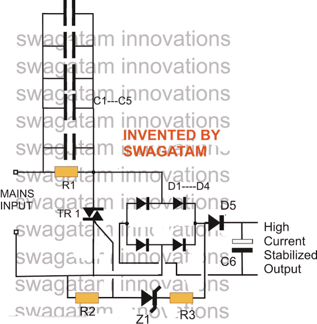
In the context of efficiency, the method used in the circuit above to regulate voltage and surge is ineffective.

To achieve the desired outcomes as suggested by the design above with no shunting valuable current, a circuit with a complete opposite reaction must be put into place, as illustrated above.
The triac is connected in a way that means that it cuts off power immediately as the output hits the designated safe voltage limitation, that has been identified by the BJT stage. This is noteworthy since the triac is not set up to discharge power.
Recent Update:
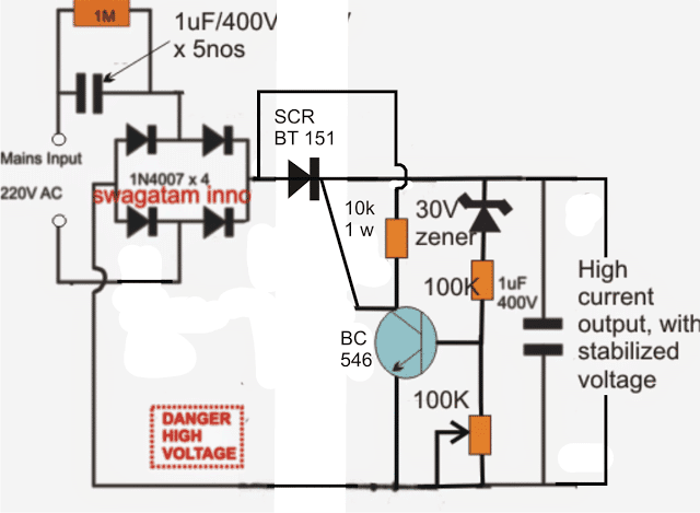
The triac could fail to operate correctly in the above-modified design because of its very odd location.
A properly setup version of the above is shown in the accompanying diagram, and it should function as anticipated.
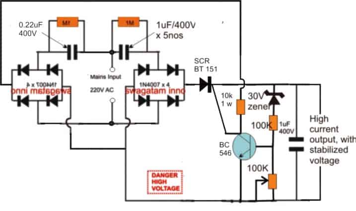
Because the SCR is positioned immediately following the bridge rectifier and the input is in the shape of DC ripples rather than AC, i decided to utilize it in place of a triac in this configuration.

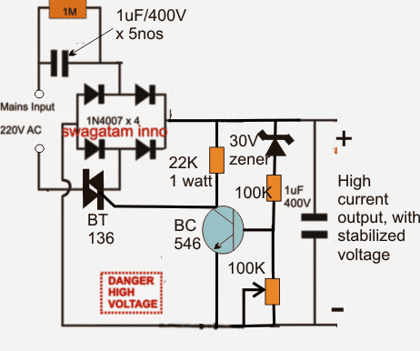
Enhancing the design above:
The output of the SCR-based transformerless power supply circuit mentioned above is spikes shielded, however the BC546 is not.
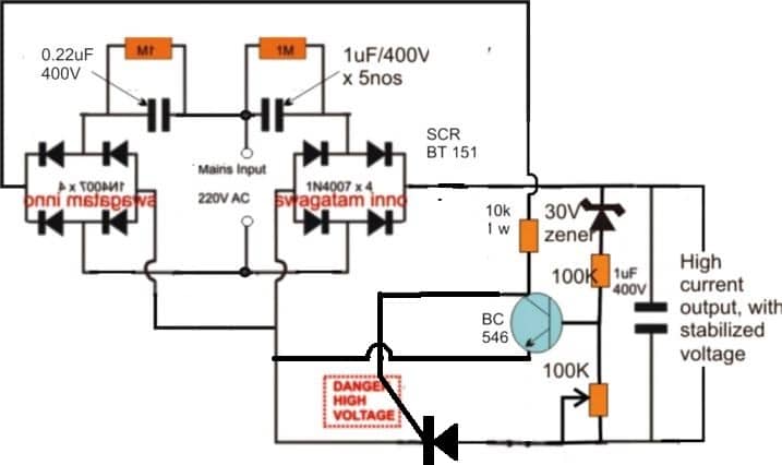
A additional low power triggering stage must be introduced to the B546 stage for the purpose to guarantee total protection for the whole circuit in addition to the BC546 driving stage. The updated design is seen below:

By moving the SCR as indicated below, the aforementioned configuration can be dramatically enhanced:
Thus far, you have examined many transformerless power supply systems featuring high current specifications and learnt about their various configuration options.
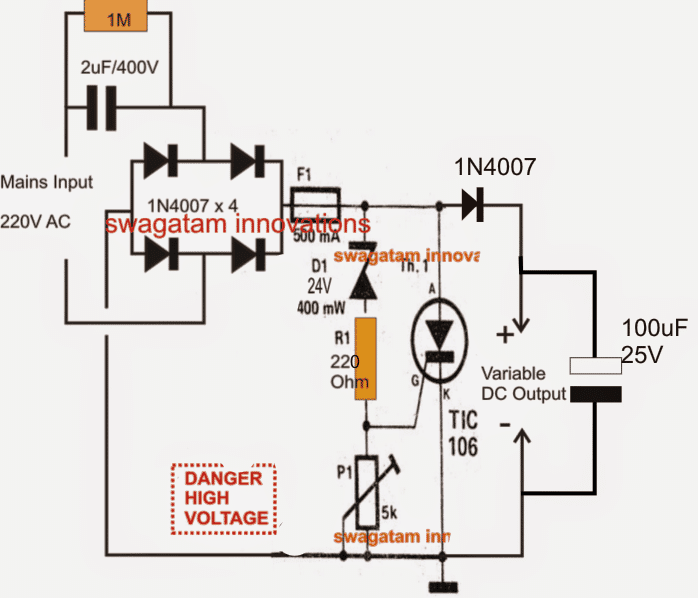
We might proceed a bit farther down and discover how to use an SCR to create an adjustable variation circuit. The described design becomes significantly more dependable with its original intent because it is surge safeguarded in addition to offering the option of obtaining a constantly varying output.
The following illustration helps to understand the circuit:
Operation of Circuits
We are all accustomed with the circuit's left side; the input portion of the capacitor, four diodes, and filter capacitor are the components of a typical, unstable fixed voltage transformerless power supply circuit.
This section's output is going to be erratic, susceptible to sudden increases in currents, and comparatively hazardous to use on delicate electronic circuits.
The circuit on the right side of the fuse is what gives it its whole new, advanced design.
Crowbar Network
Actually, that it's a crowbar network that was added for a few intriguing purposes.
Together with R1 and P1, the zener diode creates a sort of voltage clamp that determines the voltage that causes the SCR would activate.
Since P1 essentially adjusts the zener voltage between zero and its highest rating, it may be inferred that it is between zero and twenty-four volts.
The SCR's firing voltage is determined based on this modification.
The rectified DC voltage begins to grow between D1 and P1 immediately as mains power is turned on, assuming P1 specifies a 12V range for the SCR gate.
The SCR receives enough activation voltage when it hits the 12V limit and turns ON immediately, short circuiting the output terminals.
The output's tendency to short circuit typically decreases the voltage toward zero, but as soon as the voltage drop falls underneath the predetermined 12V limit, the SCR prevents the output from achieving the necessary gate voltage and returns to its non-conducting state. This circumstance permits the voltage to increase once more, and the SCR repeats the process, ensuring that the voltage never exceeds the predetermined threshold.
Because the SCR will never permits a surge to reach the output in any situation, the crowbar design likewise guarantees a surge-free output and permits operations with comparatively larger current.
Circuit Diagram