

The post details a high current, high power temperature regulator circuit using SCRs, which can be used for switching OFF a load at a predetermined temperature level
Without the special ICs this temperature regulator can be structured. It may also be used with powers up to 3.5 kVA.
How the Circuit Works
The circuit works using the concept of a two-point regulator and a thermistor functions as the temperature-sensor. Since the load current is only turned on during zero crossing of the mains, there is no need of additional interference suppression.

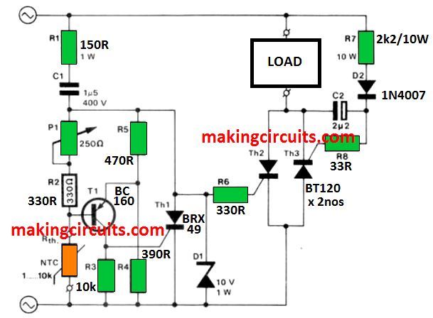
R1, C1 series combination helps to decrease the voltage of mains to a level appropriate as supply voltage to trigger T1.
Since, R1 is small as compared to reactance of C1, the current leads nearly by 90 degrees to the voltage.
When the ambient temperature is more than the given value, which is determined by the potentiometer P1, the resistance of Rth is low enough to cause T1 to conduct.
The SCR Th1 is controlled by silicon. It is supplied with gate current and turns on at the negative half cycle of the mains – because, the current through R1C1 leads the voltage. Thyristors Th2 and Th3 remains blocked when Th1 is active – this ensures that no current flows through R1, i.e. the heating element.
T1, i.e. the transistor and Th1 or the thyristor remains shut when the temperature goes below the P1-determined value. Th2 turns on when the Mains AC crosses zero, as the voltage across zener diode D1 leads the main voltage. Th3 turns on at the beginning of the negative half cycle.
C2 is being charged via R1 and D2, during the positive half cycle, therefore provides the gate current to activate Th3 , right when the negative half cycle begins.