

The post narrates the making of a simple high temperature fire alarm circuit using transistors only, and not with conventional heat sensors.
Though we don’t pay much heed to fire alarm usually, it is in fact a necessary factor that should be maintained as a de facto. Accident is unfortunate, but if you remain a bit cautious and maintain basic safety practices, you may save your property from the fire, if it ever happens to you.
While fire alarm circuit is a widely available tool in the market, many often retorts to building such component. Making a fire alarm tool is simple. All you need to gather are the components and follow specific procedure for installation to build the system.

Circuit Design of Fire Alarm Circuit
This fire-alarm circuit is designed in such a way that when the system receives temperature that exceeds to the permeable limit, this tool will automatically generate alarm.
Recommended Components
Resistors [1/4W +- 5%]
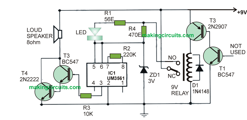
- 66ohms – R1
- 720K – R2
- 10K – R3
- 500 ohms – R4
Capacitors
1N4001 Diode – D1
Zener Diode 3V 0.5w – ZD1
3 Siren Sound Generator [UM3561] – IC1
Transistors are as follows
BC547 – Q1
BC547 – Q2
2N2907 – Q2
BC547 – Q3
2N2222 – Q4
9v Relay 100 ohms
8 ohms 1 watt Speaker
Procedure of Assembly
To define a proper tool, the proposed system will use the combination of silicon NPN transistor Q1 [BC109] and PNP Germanium Transistor Q2 [AC188]. The main reason to use both the components is for heat detection. The Q1 should be connected to Q2 and further Q2 should connect with RY1 relay.
The next part of the high temperature fire alarm circuit design process is with ICI-UM3561 where the IC that generates siren should be connected to a 3v power supply unit. In brief, connect Pin 5 and 6 of the IC to the power unit. During relay running procedure ensure that you have placed Pin 2 to the ground.
The R2 resistor over Pin 7 and Pin 8 operates to limit the oscillator frequency.
In order to boost signal from IC1 R4 resistor the output has to be sent from Q3 and Q4 transistors using the Darlington Compound process. The R4 is further connected to the Zener Diode series to control voltage supply on IC1. The R1 resistor is in series is connected to LED1 and also parallel to R4. Doing this would enable the tool working properly.